
On this page
The statement that resistor tolerance cancels in a dual-slope ADC is conditional on the circuit that performs the two integrations. A shared resistance affects both slopes equally in the ideal model. Separate input and reference paths retain their resistance ratio. For a custom ceramic resistor network, the useful specification starts with that distinction, not an unnecessarily tight tolerance on every element.
System boundary
A low-bandwidth sensor voltage, switched integration paths, integrator, reference source, zero-crossing detector and conversion timer. The equations describe a basic dual-slope converter, not every multislope or sigma-delta architecture.
Integration interfaces
| Interface | Required input | Thick film role | Validation owner |
|---|---|---|---|
| Sensor to integration path | Input range, source resistance, integration duration and selected switches. | A printed resistor may set input integration current and ramp height. | Analog designer establishes the complete input path. |
| Reference to return integration | Reference magnitude, return-path resistance and switching state. | A distinct printed reference resistor creates a ratio specification. | Converter designer verifies charge balance. |
| Integrator endpoint to timer | Comparator threshold, clock counts, reset state and observed waveforms. | Passive slope selection changes sensitivity to endpoint voltage error. | Acquisition validation owner verifies conversion timing. |
Integration risks
| Risk | Control or verification | Validation owner |
|---|---|---|
| Separate switch and source resistances are assumed to cancel. | Include the effective resistance of each active path in the phase equation. | Circuit design owner. |
| A cancelled component tolerance is allowed to saturate the integrator. | Check worst-case ramp excursion independently of the final transfer ratio. | Analog validation engineer. |
| Comparator delay is corrected by trimming a resistor ratio. | Separate count offset, endpoint error and multiplicative scale error. | Calibration owner. |
System integration decisions
- Identify the complete resistance active in each conversion phase.
- Allocate ratio stability separately from integrator ramp headroom.
- Verify endpoint and timing errors before changing the printed network.
Write down two circuits, not one resistor value
In the first phase, a selected input voltage drives the integrator for a prescribed interval. In the second, a reference of opposite polarity returns the integrator toward its starting endpoint. Draw the active current path for each phase, including the switch, source resistance and any series protection. An element disconnected during the return phase cannot be assumed to participate in cancellation.
For a ceramic thick film network, mark which physical element is shared and which elements are separate. A common package does not mean common electrical resistance. Conversely, one shared resistor need not require an exceptionally accurate absolute value merely because the converter is precise. Its allowed range still has to support current, headroom and settling throughout the conversion.
Retain the input-to-reference resistance ratio
Use positive voltage magnitudes for this derivation, with the reference applied in the polarity that reverses the ramp. The input phase moves the integrator by Vin times Ti divided by Ri and C. The return phase moves it back by Vref times Td divided by Rr and C. Equal excursions give the conversion equation below.
The capacitor cancels when the same effective capacitance applies to both phases and the endpoint is restored. If Ri equals Rr because the same effective resistance is used, the resistor term also cancels. If different paths are used, their ratio remains. Include source and switch resistance where it is significant; a nominally matched printed pair cannot cancel an unequal external series contribution.
Vin*Ti/(Ri*C) = Vref*Td/(Rr*C); Vin = Vref*(Ri/Rr)*(Td/Ti)
- Vin and Vref are input and reference voltage magnitudes in volts.
- Ti and Td are input and return integration durations in seconds.
- Ri and Rr are the effective input and reference resistances in ohms; C is common integration capacitance in farads.
Ideal linear integration with opposite ramp polarities, stable quantities within each phase, equal initial and final endpoints, and no residual charge, leakage or switching injection.
Calculate the retained error before specifying a trim
Assume a 2.500 volt reference, a 100 millisecond input interval, and effective resistances Ri of 100.1 kilohms and Rr of 100.0 kilohms. For an actual 1.000 volt input, the predicted return interval is approximately 39.960 milliseconds. These are deliberately chosen circuit values, not a product accuracy claim.
Firmware that omits the resistance ratio would report approximately 0.999001 volt. Applying the actual ratio of 1.001 restores 1.000 volt in the ideal model. A common ten percent change in both resistances would leave the ratio unchanged, whereas a change in only one path would not. This tells the buyer whether the drawing needs absolute resistance control, ratio control, or both for different reasons.
| Quantity | Assumed or calculated value | Interpretation |
|---|---|---|
| Ri/Rr | 1.001 | Retained multiplicative factor |
| Return interval | 39.960 ms approximately | Balances the input phase |
| Result without ratio correction | 0.999001 V approximately | About 999 ppm low |
| Result including ratio | 1.000 V | Ideal corrected value only |
Cancellation does not protect the integrator from clipping
A component can disappear from the final transfer equation while remaining essential to valid operation. With a 1 volt input, 100 millisecond integration time, 100 kilohm input resistance and 1 microfarad capacitor, the ramp excursion is 1 volt. Halving the capacitor doubles that excursion even though the ideal conversion ratio remains unchanged.
Check both input polarities, maximum signal, accumulated interference and the initial integrator level against the active amplifier's usable swing. Clipping destroys the charge history needed by the second phase. Do not interpret a clipped waveform as evidence that the reference resistor is wrong. Include enough observation of the ramp to establish that the ideal cancellation model is applicable to the assembled circuit.
Use the clock ratio only within its validity boundary
If both intervals are measured with the same constant clock frequency, Td divided by Ti equals their count ratio. A common frequency offset then affects both intervals equally. This does not mean clock behaviour is irrelevant. A frequency change between phases, missing edge, asynchronous switching delay or inconsistent start event can change the measured ratio.
Keep the integration-start, reference-switch and endpoint-detection events explicit in firmware records. For a fixed input count, identify whether the timer starts at the command or the actual analog switch event. A reproducible delay can be characterized; an uncontrolled delay cannot be removed merely by increasing nominal counter resolution. Preserve those timing definitions when moving the resistor network into a different assembly.
Convert endpoint uncertainty into time error
During reference return, the ramp magnitude per second is Vref divided by Rr and C. An endpoint voltage displacement therefore corresponds to a timing displacement equal to that voltage divided by the return slope. With 2.5 volts, 100 kilohms and 1 microfarad, the return slope is 25 volts per second. An assumed 100 microvolt endpoint displacement corresponds to 4 microseconds.
For the 100 millisecond integration example with equal path resistances, that time displacement maps to 100 microvolts of input-equivalent error. Its sign depends on the endpoint and detection direction. Separate a fixed endpoint displacement from delay, noise and residual-charge history. A resistor ratio trim corrects a scale factor; it does not generally correct an input-dependent endpoint or polarity-dependent conversion defect.
Validate phase history as well as static gain
Exercise a sequence that includes positive and negative inputs where supported, small values, large values and transitions between them. Retain ramp waveforms and raw counts before applying calibration coefficients. A history-dependent result following a large input suggests a different investigation from a constant proportional error at every level. Check the reset and integration capacitor behaviour before asking for a new resistor value.
Keep the reference source, timing and thermal condition constant when comparing resistor networks. If only the ratio changed, predict its sign and magnitude before measuring. If the integration time or capacitance also changed, the comparison includes a different endpoint sensitivity and ramp excursion. The validation record should distinguish those effects instead of assigning every improvement to tighter printed resistance tolerance.
Specify the passive network by its actual conversion role
Send a phase-annotated schematic with Ri and Rr defined at their electrical boundaries. State the allowable ratio change, absolute resistance range required for ramp operation, expected voltage and current, and the temperature conditions of the two paths. Indicate whether external source or switch resistance is included in the measured acceptance value. This avoids a nominal resistor specification that does not represent the complete converter.
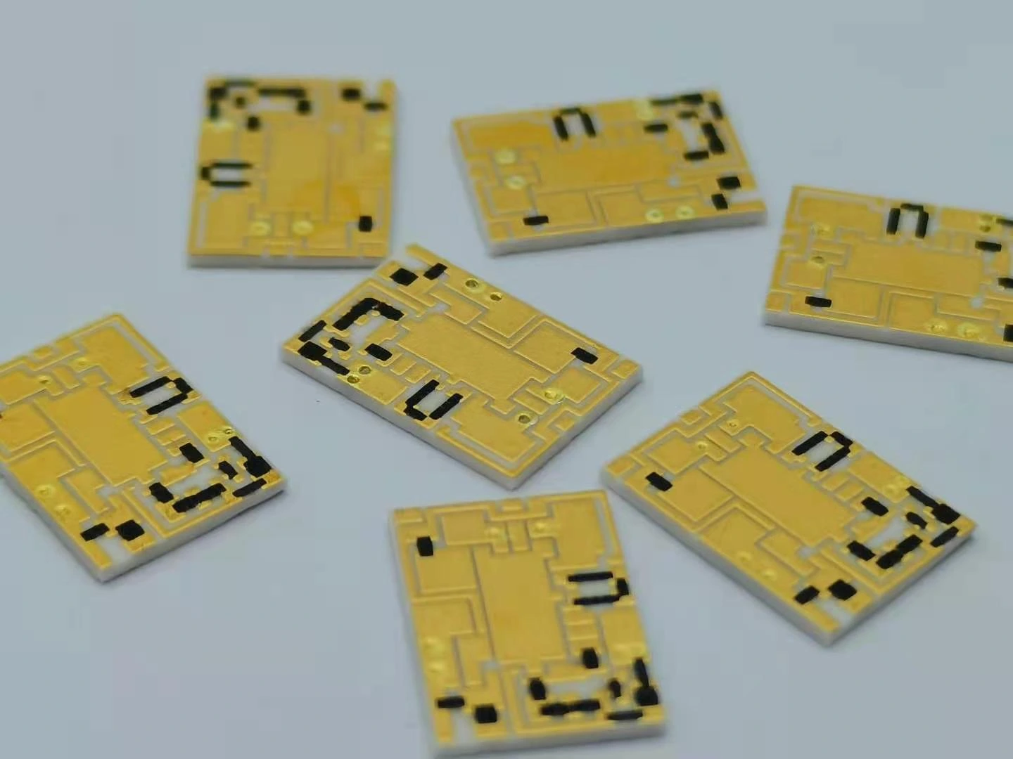
ChipSimple can review the drawing-defined ceramic resistor network and its passive measurement requirements. The customer's electronics team remains responsible for the active integrator, reference, switching and conversion algorithm. Keep the network acceptance data separate from complete-channel calibration so an approved passive part is not mistaken for proof that every conversion-phase error has been controlled.
Review a resistor network for integrating conversion
Identify both integration phases so the requested tolerance controls the error that survives cancellation.
- Phase-annotated circuit with input and reference path resistances.
- Reference magnitude, input range and clock-count definitions.
- Integrator capacitance, usable ramp range and endpoint observations.
- Ratio and absolute resistance allocations under operating conditions.
- Raw count and waveform records for the relevant input sequence.
The drawing-upload form loads as you reach this section.