
On this page
A fuel-level sender resistor card converts contact position into an electrical value, but the installed indication begins with the tank and float mechanism. This guide defines the chain from liquid height through arm rotation and card travel to the gauge input. Tank-volume conversion, diagnostics and final indication accuracy remain owned by the vehicle or equipment integrator.
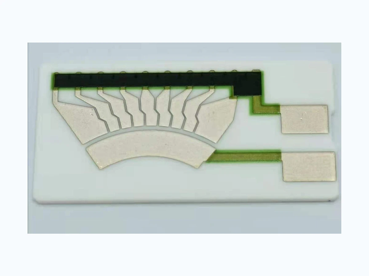
For a drawing-specific part, review the Fuel level sensor resistor card construction, product evidence and quotation inputs alongside this method. Prepare the curve and error worksheet with your operating conditions.
System boundary
Fuel surface and tank geometry through float, arm, pivot, wiper, resistor card, harness and gauge input.
Integration interfaces
| Interface | Required input | Thick film role | Validation owner |
|---|---|---|---|
| Liquid to float | Fuel specification, density range, float displacement and installed liquid-height datum. | The card senses position delivered by the mechanism; it does not measure buoyancy or tank volume. | System integrator verifies buoyancy and clearance in the specified fluid. |
| Float arm and pivot | Pivot coordinates, arm length, angle convention, stops and height-to-angle mapping. | Track travel must cover the released wiper sweep within the designed contact region. | Mechanism designer verifies travel and hysteresis; supplier checks drawing-defined card limits. |
| Wiper to track | Wiper material, force, sweep speed, target resistance points and allowable discontinuity. | The printed track and collector form the specified electrical path at each reference position. | Integrator defines contact-pair testing; supplier verifies agreed card geometry and electrical points. |
| Card terminals to harness | Terminal drawing, joining method, harness resistance and connector loads. | Terminal geometry and resistance affect the electrical boundary measured at the card. | Harness owner verifies connection and series drop; supplier verifies the terminal interface. |
| Harness to gauge | Excitation, input impedance, filtering, diagnostic thresholds and height-to-volume conversion. | The card supplies position-dependent resistance under the declared electrical load. | Electronics and vehicle integrator validates gauge conversion, diagnostics and final indication. |
Integration risks
| Risk | Control or verification | Validation owner |
|---|---|---|
| Arm obstruction | Sweep the mechanism through empty, full and intermediate positions in the installed tank envelope. Record contact with baffles, stops or walls. | Mechanism and tank integrator |
| Float interference | Check buoyancy, clearance and usable travel at the specified fluid conditions and vehicle attitudes. | Tank and sender integrator |
| Contact dropout | Record resistance in forward and reverse sweeps under agreed force, speed, media and excitation. Separate contact interruption from gauge filtering. | Contact-pair validation owner with card supplier support |
| Harness fault | Compare card-terminal and gauge-input measurements. Evaluate open and short conditions using the system diagnostic plan. | Harness and electronics integrator |
| Incorrect volume conversion | Compare height, angle, resistance and displayed volume at the same reference points. Validate tank conversion separately from card linearity. | Gauge software and vehicle integrator |
System integration decisions
- Define liquid height, usable float travel and arm rotation from the actual tank section.
- Map arm angle to wiper position before specifying the resistance curve.
- Allocate harness, excitation, readout and volume-conversion errors outside the resistor-card boundary.
Start at the tank, not at the resistance value
The controlled variable may be fuel height, usable volume or a displayed fraction, and those are not interchangeable in an irregular tank. Freeze the installed tank cross-section, vehicle attitude convention, unusable volume and reference plane before defining sender travel. The component boundary begins where the float mechanism applies motion to the wiper and ends at the specified card terminals. A bench resistance reading therefore cannot establish displayed fuel volume by itself.
Name each physical handoff: fuel surface to float, float to arm, arm to pivot, pivot to wiper, wiper to track, track to terminals, terminals to harness and harness to gauge electronics. Record the owner, datum and permissible load at every handoff. This prevents a linkage error, connector drop or software conversion error from being reported as a resistor-card defect without a discriminating test.
Convert tank geometry into required sender motion
Use the real internal tank profile, including slopes, baffles, sumps, pump modules and regions the float cannot enter. At selected liquid heights, calculate or measure the corresponding contained volume. The resulting height-to-volume curve may have changing slope. Choose the height interval that must be sensed and show where the float center sits relative to walls and obstacles throughout that interval.
Check the sender in the installed orientation and at the integrator-defined attitudes. A level surface in a tilted tank can move the float toward a baffle or alter the height seen near the pivot. Preserve clearance envelopes at empty, full and intermediate positions. Mechanical stops should protect the card from overtravel without truncating the required measurable volume range.
Map float-arm rotation to wiper travel
Define pivot coordinates, effective arm length, float-center offset, shaft direction and the relationship between shaft angle and wiper position. For a simple planar arm, vertical float displacement can be written as h(theta)=h_p+L sin(theta), subject to the actual installed angle convention. Linkage bends, lost motion and nonplanar motion require the integrator model rather than an assumed sine curve.
Differentiate the kinematic relation to find sensitivity: dh/dtheta=L cos(theta). Near angles where cosine becomes small, substantial rotation may create little height change, or a small height uncertainty may create a large inferred angular uncertainty. Place resistance-curve breakpoints using the real kinematic and tank-volume slopes instead of distributing them evenly only because the printed arc is uniform.
Calculate the installed height-to-resistance mapping
At each controlled height, follow the mapping h to theta, theta to wiper coordinate s, and s to resistance R. The local installed gain is G_h=dR/dh=(dR/ds)(ds/dtheta)(dtheta/dh). Keeping the three factors visible identifies whether a steep gauge response comes from track design, linkage ratio or arm geometry. It also shows where one uniform track slope cannot create a uniform volume indication.
For an illustrative average, a 180 ohm resistance span over 300 mm of useful height gives 0.60 ohm per millimetre. That arithmetic ignores tank shape and changing linkage sensitivity. It is not a product tolerance or a company capability. A project worksheet evaluates the gain at multiple heights and carries measured bounds for pivot location, arm length, contact position and resistance.
G_h = dR/dh = (dR/ds)(ds/dtheta)(dtheta/dh)
- h: fuel height in the declared tank reference
- theta: installed arm or pivot angle
- s: wiper coordinate on the resistor card
- R: terminal resistance at the specified measurement boundary
Use the actual tank, installed sender orientation, linkage definition, card geometry and reference state.
Define excitation, harness and gauge loading
State whether the card is read as resistance, divider voltage, current, ratio or a filtered controller value. Provide excitation level and tolerance, pull-up or reference resistance, input impedance, connector and harness resistance, ground arrangement, ADC range, sampling interval and conversion equation. Measure at the nodes used by the gauge rather than at convenient card pads that bypass installed wiring.
Separate four observations when diagnosing the chain: independent mechanical height, shaft or wiper position, card-terminal resistance and gauge-input value. A stable card resistance with a changing gauge input indicates wiring or electronics. Correct gauge input with an incorrect height relationship points upstream to tank geometry or linkage. Preserve raw readings before software damping or display quantization.
Discriminate tank, mechanism, contact and readout faults
Arm obstruction often appears as a plateau in wiper position while liquid height continues to change. Pivot backlash creates direction-dependent position around reversals. Contact dropout produces a short electrical discontinuity without equivalent mechanical motion. Harness intermittency changes the terminal-to-gauge relationship. An incorrect tank conversion can produce repeatable electrical signals and still display the wrong volume.
Diagnose from the first interface where the reference and observed value diverge. Do not adjust the printed curve to compensate for an unidentified float collision or a software scaling mistake. Retain the installed state before bending an arm, moving a stop, cleaning a contact or changing filtering, because those actions can erase the evidence needed to assign ownership.
| Observed pattern | Likely boundary | Discriminating check | Disposition |
|---|---|---|---|
| Wiper position plateaus while height changes | Tank or arm interference | Observe float and arm against height reference | Hold installed mechanism |
| Resistance opens with continuous arm motion | Wiper-to-track contact | Measure card terminals with synchronized motion | Review contact event |
| Card resistance correct but gauge input shifts | Harness or connector | Compare card-terminal and gauge-input nodes | Separate wiring contribution |
| Gauge input repeatable but volume wrong | Tank conversion or software map | Compare height, volume reference and conversion table | Integrator reviews mapping |
Validate the complete installed transfer chain
Use a representative tank or a justified fixture that reproduces pivot, obstacles, sender orientation and electrical interfaces. Exercise filling and draining directions because buoyancy, friction and backlash may be direction-dependent. Sample endpoints, reversal regions, tank-shape transitions and positions near internal obstacles. Record fuel substitute properties if a substitute fluid is used and state which buoyancy or compatibility effects it does not reproduce.
Freeze valid-run criteria before viewing confirmation results. Synchronize liquid-height reference, arm angle or wiper coordinate, terminal resistance and gauge input. Independent assemblies estimate installation variation; repeated readings on one sender estimate observation repeatability. Validation acceptance comes from the integrator-controlled requirement. This page claims no vehicle approval, regulatory compliance or functional-safety status.
Allocate system risks and diagnostic response
The risk review includes false empty, false full, stuck indication, intermittent dropout and an apparently plausible but biased reading. For each event, the integrator records operational consequence, detectability, diagnostic timing and safe or degraded response. Dual sampling or filtering may improve observation but cannot remove a mechanical common cause such as an obstructed float.
The resistor card can be evaluated for its drawing-defined transfer and contact behaviour at specified interfaces. Tank crashworthiness, fuel compatibility of the complete sender, vehicle diagnostics, warning strategy and remaining-range calculation belong outside that component evidence. Unknown requirements remain open in the project record rather than being converted into implied capability.
Control the installed state through change
Link tank drawing, baffle arrangement, float, arm, pivot, stop, card, wiper, connector, harness, gauge electronics and conversion software by revision. Store the synchronized transfer data with assembly genealogy and installed orientation. Identify which tank regions and attitudes were represented in validation. A card with the same nominal resistance span is not automatically equivalent if its travel, contact geometry or terminal reference differs.
Revalidate the affected mapping after changes to tank shape, sender mounting, pivot position, arm length, float, stop, track curve, wiper, harness, excitation, input impedance, filtering or software conversion. State which earlier measurements remain comparable. A mechanical correction should not be credited to the card, and an electrical correction should not conceal unresolved interference.
RFQ inputs for a fuel-level sender resistor card
Provide the tank section or controlled height-to-volume data, sender mounting coordinates, useful height range, pivot and arm geometry, float envelope, direction of motion, mechanical stops and allowed contact travel. Identify the resistance or voltage curve required at named reference positions. Include terminal drawing, wiper definition, excitation, gauge input, harness assumptions, environment, duty history, quantity and failure consequence.
Send the integrator-owned acceptance criteria and indicate how height or volume will be referenced during validation. List known risks such as baffle contact, tilt sensitivity, reversal hysteresis or diagnostic thresholds. If tank geometry, mechanism loading, electrical input or safe response is not defined, mark it for application review. Missing system values are not guessed during quotation.
Fuel-sender integration inputs
Submit the installed geometry and electrical chain required to evaluate the card interface.
- Tank height-to-volume definition, installed sender coordinates and float-clearance envelope.
- Pivot, arm, stops, wiper travel and required resistance curve.
- Excitation, harness, gauge-input and conversion details.
- Environment, duty, quantity, validation criteria, risk owner and unresolved questions.
The drawing-upload form loads as you reach this section.