
On this page
Oil level is an installed-system quantity. Sump shape, oil condition, vehicle or machine attitude, float buoyancy, guide friction, resistor-card contact and instrument damping all influence the reported value. This method keeps those contributions separate so drawing-specific card evidence is not mistaken for qualification of the complete lubrication system.
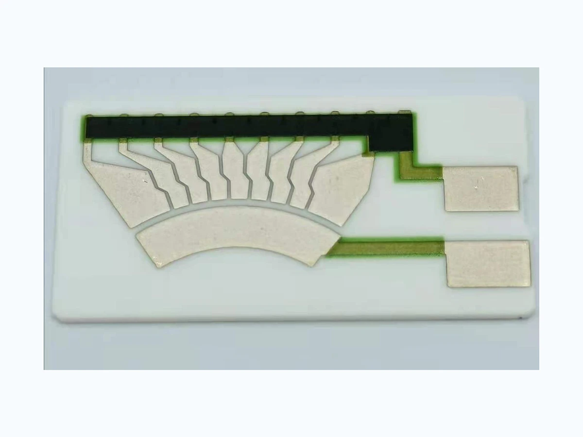
For a drawing-specific part, review the Fuel level sensor resistor card construction, product evidence and quotation inputs alongside this method. Prepare the curve and error worksheet with your operating conditions.
System boundary
Oil free surface in the specified sump through float or guide mechanism, wiper, resistor card, wiring and instrument input
System integration decisions
- Define the sump reference and oil condition for every level point.
- Separate float equilibrium and guide friction from card resistance.
- Verify the electrical and display chain with synchronized physical references.
Define the sump level reference and operating state
Establish where oil height is measured and what the measurement represents. A static service-fill reference, a running-engine sump level and a transient level during acceleration may differ substantially. Identify the sump datum, installed attitude, drain-back time, pump state and temperature for every reference point. If the required displayed quantity is usable oil volume, provide the controlled height-to-volume relation rather than asking the sender card to infer it.
Map internal walls, pickup hardware, windage trays, baffles and regions that can trap or redirect oil. Show the float envelope against those features over the useful range. A nominal vertical clearance on a drawing may disappear when the machine tilts or oil motion loads the float laterally. The integrator owns the operating states and the interpretation of short-duration level movement.
Model buoyancy, immersion and dynamic lag
At equilibrium, buoyant force equals the displaced oil weight and the effective downward mechanical load. A simplified expression is rho_oil g V_displaced = W_effective. Density, float volume, trapped gas, guide friction and linkage load determine the immersion needed to move the contact. Record the oil or approved substitute used for evaluation; equal liquid height with a different density may produce a different float position.
Viscosity and restricted clearances affect response time rather than only equilibrium. During filling, draining or machine motion, the float may lag the free surface or stick on a guide. Measure rising and falling paths separately. Do not adjust the resistance curve to cancel a friction effect that has not been bounded, because wear, contamination and temperature can change that compensation later.
Translate float position into contact travel
Describe whether the float slides directly, rotates an arm, drives a magnetically coupled follower or uses another mechanism. Give the guide axis or pivot coordinates, useful travel, stops, preload and the coordinate of the wiper on the resistor card. The mechanical transfer must be monotonic over the required range unless the instrument explicitly handles another relation.
Measure backlash, lost motion and return position at representative oil states. A resistance value should be paired with both oil-height reference and actual wiper coordinate. That three-way record distinguishes sump or float error from track conversion. Protect the card against overtravel when oil surge or service handling pushes the mechanism beyond the normal indicating range.
Calculate oil-height indication error
Use e_h = h_indicated - h_actual at each declared sump state. The indicated height is derived through the instrument conversion, while actual height comes from an independent reference tied to the sump datum. Plot error against height, direction, temperature, pump state and attitude. A single full-to-empty span cannot show a localized baffle interaction or a friction-induced reversal difference.
If the instrument corresponds to 42 mm while the independent reference is 40 mm, the system error is +2 mm for that condition. This example establishes sign convention only. It is not an accuracy claim or an acceptance limit. Attribute the +2 mm only after comparing float position, contact coordinate, card resistance, wiring voltage and instrument conversion.
e_h = h_indicated - h_actual
- e_h: installed oil-height indication error
- h_indicated: height derived by the declared readout conversion
- h_actual: independent sump-referenced oil height
Oil state, attitude, pump condition, direction of level change and acquisition time are recorded.
Define card excitation and instrument damping
Provide the resistor-card terminal definition, excitation circuit, supply tolerance, reference resistor, input impedance, wiring resistance, ground scheme and acquisition rate. Oil-level instruments often damp movement to suppress transient slosh. Preserve undamped electrical data as well as displayed output so a filter delay is not misclassified as float sticking or contact dropout.
Check response at card terminals and instrument input simultaneously. A discontinuity at both locations with continuous float travel suggests wiper-to-track loss. A stable terminal value with an input disturbance points to wiring or grounding. A correct electrical input followed by the wrong displayed level belongs to scaling, damping or software, not automatically to the printed track.
Diagnose fluid, mechanism, contact and readout causes
A level error that changes with oil density, temperature or pump state first challenges float equilibrium and sump conditions. Direction-dependent lag challenges friction or hydraulic restriction. A sharp resistance open at a repeatable contact position challenges the wiper interface. Random changes between sender and instrument nodes challenge wiring. Stable raw input with delayed display challenges damping.
Preserve the installed evidence before cleaning a guide, bending an arm, changing contact force or editing the conversion table. Those actions alter different boundaries and can remove the signature needed for ownership. The system integrator decides the consequence of a false oil indication and the appropriate diagnostic or safe response.
| Signature | Boundary under test | Reference comparison | Next action |
|---|---|---|---|
| Bias changes with oil temperature or state | Oil and float equilibrium | Height versus actual float position | Review fluid and buoyancy inputs |
| Rising and falling paths differ | Guide or linkage friction | Float coordinate versus direction | Review mechanical hysteresis |
| Electrical open with continuous motion | Wiper and track | Terminal resistance versus contact coordinate | Hold card/contact state |
| Terminal stable but display delayed | Instrument damping | Raw instrument input versus display | Integrator reviews filter |
Validate declared sump states and duty history
Use the specified sump or a fixture whose geometry, attitude and float constraints are justified. Exercise service fill, running condition, drain-back, rising and falling level, temperature states and relevant tilt or acceleration cases. A substitute oil must have its density and viscosity recorded, and the protocol must state which chemical or long-term effects it cannot reproduce.
Synchronize independent oil height, float position, wiper coordinate, terminal resistance, instrument input and displayed value. Establish invalid-run and retest rules beforehand. Independent mechanisms test assembly variation; repeated acquisition on one mechanism tests observation repeatability. Acceptance comes from the integrator requirement, and this page conveys no vehicle, engine or regulatory approval.
Control system-level oil indication risks
Consider false low, false normal, false high, frozen output and intermittent output separately. Their consequences may differ between maintenance indication, operator warning and automatic protection. Record detection method, allowed diagnostic latency, degraded response and owner. Filtering can hide a short contact open, while a plausible stable signal can conceal a stuck float.
The resistor card can be assessed at specified travel, loading and electrical conditions. Oil compatibility of the full sender, sump hydrodynamics, warning strategy and engine-protection logic belong to system owners. Unknown hazard classification, diagnostic coverage or safe state remains open; no certification or functional-safety compliance is claimed.
Configuration control and RFQ preparation
Control the sump, baffles, pickup, float, guide or arm, stops, wiper, card, connector, wiring, instrument circuit and conversion logic by revision. Revalidate affected evidence after changes to oil grade assumptions, installed attitude, geometry, friction, travel, contact force, excitation, input impedance, damping or scaling. A matching resistance span does not prove installed equivalence.
For RFQ review, supply sump and sender drawings, datum and attitude definitions, useful height or volume range, float and mechanism geometry, terminal curve, excitation, readout circuit, temperature, oil state, duty, quantity and failure consequence. Identify the integrator acceptance criteria and diagnostic ownership. Missing fluid, mechanism or controller inputs stay explicit rather than being guessed.
Oil-level integration inputs
Provide the sump, mechanism and readout definition for the intended operating states.
- Sump drawing, datum, attitudes, operating oil states and height-to-volume data.
- Float, guide or arm, stops, wiper travel and resistor-card curve.
- Excitation, wiring, instrument input, damping and conversion details.
- Duty, environment, quantity, acceptance, diagnostic owner and unresolved questions.
The drawing-upload form loads as you reach this section.