
Overview
A temperature sensor reports conditions at its own sensing element, not the hottest printed trace, the complete heater surface, or the heated medium automatically. Integration therefore begins by defining the controlled variable and the thermal path between heater, substrate, interface, load, sensor, and ambient. Sensor type, placement, attachment, wiring, insulation, response time, controller tuning, calibration, redundancy, and fault handling must be developed as one system. A neat sensor location can still produce overshoot or unsafe blind spots when the load changes, contact is lost, flow stops, or the sensor becomes detached.
Failure controls
These are review prompts, not evidence that every risk applies or that every test is available.
- A
Controlling a convenient sensor location while the actual heater trace, terminal, interface, or load exceeds its own limit.
- B
Copying bare-sensor accuracy or response specifications to an installed sensor without attachment, lead, readout, gradient, and lag errors.
- C
Placing the sensor in a thermally quiet region that responds too slowly to contact loss, flow loss, startup overshoot, or local hot spots.
- D
Using one sensor for control and protection without analyzing common-cause detachment, wiring, calibration, controller, and placement failures.
- E
Changing adhesive, bond-line thickness, sensor package, routing, firmware, filter, clamp, load, or airflow after validation without re-evaluation.
- F
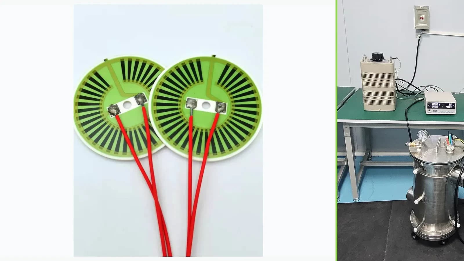
Describing a photographed test scene as proof of calibration, range, control accuracy, safety function, or company qualification capability.
Engineering review matrix
Each row links a design variable to evidence that can support a drawing or release decision.
| Variable | Control question | Verification route |
|---|---|---|
| Controlled variable | Define whether the controller regulates heater surface, substrate, interface, load, fluid, air, or another measured quantity and specify dynamic and steady limits. | Compare the control signal with independent measurements at the actual controlled location throughout the defined operating matrix. |
| Sensor type and readout | Name sensor construction, nominal characteristic, excitation, lead configuration, converter, reference, filtering, sample rate, resolution, isolation, and calibration method. | Calibrate the assembled measurement chain and include lead, electronics, self-heating, quantization, and repeatability in uncertainty. |
| Placement and attachment | Dimension coordinates, orientation, bond line or contact pressure, protective layer, lead path, thermal mass, strain relief, and distance from heater, terminals, edges, and load. | Inspect installed position and attachment and correlate time-resolved reading with independent mapped temperatures across samples. |
| Thermal boundary and lag | Specify substrate and interfaces, mounting pressure, load mass, flow, airflow, convection, radiation, insulation, ambient, cycling, and degraded-contact states. | Measure step and disturbance response in the released assembly rather than relying on a bare-sensor time constant. |
| Controller interaction | Define setpoint, hysteresis or control law, output modulation, power limit, anti-windup, startup, overshoot, sampling, filtering, communication, and safe output state. | Run nominal, tolerance, disturbance, and fault tests while logging sensor input, controller output, electrical power, and independent temperatures. |
| Fault detection | Enumerate open, short, drift, detachment, swapped leads, common-mode leakage, frozen data, controller error, load loss, flow loss, and over-power conditions. | Inject each owned fault or justified surrogate and confirm detection time, diagnostic coverage, safe action, reset, and post-fault condition. |
| Lifecycle and change control | Include assembly heat, cure, humidity, chemicals, vibration, wire movement, cycling, aging, calibration interval, replacement, firmware, component, adhesive, and layout changes. | Repeat drift, response, insulation, and functional checks on configuration-linked samples after representative exposures and controlled changes. |
Controlled model
Sensor location, lag, and control-observation model
Separate the temperature being controlled from the temperature being measured. A first-order lag can help expose overshoot risk, but the real system can contain several thermal masses, nonlinear heat transfer, controller delays, sensor self-heating, wiring errors, and changing contact. Validation must compare the sensor signal with independent measurements at risk-relevant locations.
τ dT_s/dt + T_s = T_localFirst-order screen for a sensor temperature following its local attachment temperature.
- Units
- τ in s; T in °C or K
- Use boundary
- A simplified single-time-constant model. Attachment, sheath, substrate, load, flow, radiation, controller sampling, and filtering may create multiple delays or nonlinear behavior.
e(t) = T_set − T_s(t)Defines controller error between setpoint and measured sensor temperature.
- Units
- e and T in °C or K differences
- Use boundary
- A small error at the sensor does not prove safe trace, substrate, terminal, medium, or housing temperatures. Control law and actuator limits are separate.
ΔT_offset = T_risk − T_sDefines location-dependent difference between a risk-relevant temperature and sensor reading.
- Units
- K
- Use boundary
- Offset can change with power, load, flow, contact, ambient, mounting, and time; it cannot be treated as one constant unless validated over the complete state matrix.
Decision comparison
| Decision | Route A | Route B | Verification |
|---|---|---|---|
| Sensor near the printed heater versus near the controlled load | Near-heater placement can detect rapid local heating but may not represent the load or medium and can be sensitive to trace pattern and attachment. | Load-side placement can represent useful output better but may respond slowly or miss a local heater hot spot during contact loss. | Instrument heater, interface, load, sensor, and fault-relevant locations simultaneously through startup, steady duty, changing load, and defined abnormal states. |
| Printed sensor versus attached discrete sensor | An integrated printed element can reduce assembly parts but requires a compatible material, routing, calibration, isolation, and readout strategy. | A discrete RTD, thermistor, or thermocouple may offer a known sensing route but adds attachment, lead, profile, strain, and thermal-contact variables. | Qualify the exact sensor, attachment, wiring, readout, and heater stack; do not transfer response or accuracy from a bare sensor data sheet. |
| Single control sensor versus independent protection | One sensor simplifies control but creates common-cause risks from detachment, wiring, calibration, placement, controller, or local gradients. | A separate limiter or independent observation can address selected faults but only when independence, location, diagnostics, and safe action are explicit. | Inject open, short, drift, detachment, frozen reading, load loss, flow loss, and controller faults and confirm the defined detection and safe response. |
- Calibration of the sensing element does not remove installation error, location offset, thermal lag, lead error, controller quantization, or drift.
- A process firing temperature must never be used as the heater or sensor operating-temperature rating.
Heater-sensor integration workflow
The order makes assumptions and ownership visible before a result is promoted to a requirement.
- 01
Define controlled and protected temperatures
Name the useful controlled variable and every separate risk limit: printed-trace proxy, substrate, dielectric, terminal, joint, load, medium, enclosure, and accessible surface. State warm-up, overshoot, steady, cycling, standby, ambient, flow, contact, and fault conditions.
- 02
Select a sensing architecture
Compare printed resistor, RTD, thermistor, thermocouple, semiconductor, or other project-approved sensing routes by range, sensitivity, linearity, drift, wiring, isolation, response, attachment, readout, interchangeability, and material compatibility without assuming availability or company capability.
- 03
Map placement and thermal paths
Draw heater lanes, substrate, interfaces, load contact, flow, insulation, terminals, heat sinks, sensor body, attachment, and leads. Predict hot, cold, fast, and slow locations under nominal and degraded boundaries; reserve space and routing without disturbing the heater pattern.
- 04
Design measurement and control
Specify excitation, lead compensation, filtering, sampling, conversion, calibration points, tolerances, controller law, output limits, startup behavior, diagnostics, independent protection, and safe state. Keep control performance separate from the sensor manufacturer's bare-element specifications.
- 05
Instrument the production-intent assembly
Use independent calibrated references at fixed drawing coordinates, synchronized voltage and current capture, controlled ambient and load states, and documented attachment. Compare sensor reading with risk-relevant temperatures through transients and steady conditions.
- 06
Validate faults and freeze configuration
Test open, short, offset, drift, detachment, wrong wiring, frozen reading, contact loss, flow loss, supply error, and controller failure as applicable. Freeze sensor, attachment, placement, wiring, firmware, calibration, mounting, and change triggers with the accepted evidence.
Reference boundary
Public method sources
These sources support the engineering method and terminology used in this technical guide. They do not establish a ThickFilmPCB material list, capability limit, customer result, certification, or finished-product specification.
- 01NIST ITS-90 Thermocouple Database
Supports reference functions and coefficients for recognized thermocouple types within the database scope only. It does not select a sensor, validate an installation, or establish ChipSimple temperature-measurement capability.
- 02NIST Technical Note 1297 — measurement uncertainty
Supports identifying and reporting sensor, calibration, installation, readout, repeatability, and model uncertainty. It provides no application accuracy, response, or safety limit.
- 03Heraeus Electronics — Thick Film Heaters overview
Supports treating sensing, control, material stack, substrate, printed heater, and application heat transfer as a coupled system at a general level; supplier examples are not ChipSimple performance evidence.
Inputs for a practical review
Unknown values may be labelled unknown. The review should convert uncertainty into an explicit decision or validation task.
Send Drawings- 01
Controlled temperature and separate maximum limits for heater, substrate, terminal, load, medium, enclosure, and accessible surfaces.
- 02
Supply, heater resistance, power modulation, controller, duty, warm-up, overshoot, steady, cycling, standby, and fault behavior.
- 03
Sensor type, characteristic, package, excitation, wiring, converter, calibration, accuracy allocation, response, diagnostics, and replacement policy.
- 04
Dimensioned heater, sensor, attachment, protection, lead, terminal, mounting, interface, load, flow, insulation, and enclosure geometry.
- 05
Ambient range, fluid or airflow, contact pressure, load variation, vibration, humidity, chemicals, assembly heat, and lifecycle exposures.
- 06
Independent measurement locations, instrumentation, sampling, uncertainty, state matrix, fault injection, acceptance criteria, and reports.
- 07
Prototype quantities, sensor and mounting variants, firmware revision, traceability, substitutions, change control, and final qualification ownership.