
On this page
A constant sender output can be correct when the liquid level is stable. It can also result from a trapped float, a frozen data value or a mechanical disconnect. The waveform alone does not identify which state exists. A defensible stuck-float diagnostic first asks whether the application supplied enough independent evidence that the float should have moved, then separates mechanical, electrical and software explanations.
System boundary
The diagnostic spans liquid change, float motion, contact position, card output and receiver processing. The resistor card alone cannot prove that liquid level or the float should have moved.
Integration interfaces
| Interface | Required input | Thick film role | Validation owner |
|---|---|---|---|
| Liquid inventory | Independently measured filling, withdrawal or level movement | No independent measurement of liquid flow | Tank or equipment integrator |
| Mechanical sender | Float, arm and wiper motion | Convert contact position into the specified electrical relationship | Sender assembly designer |
| Receiver diagnostics | Excitation, acquisition, timestamps and fault logic | Present the reviewed resistance and contact interface | Electronics and software owner |
Integration risks
| Risk | Control or verification | Validation owner |
|---|---|---|
| Normal stationary operation is reported as a jammed float | Require sufficient independent level-change evidence | Diagnostic developer |
| Electrical continuity is mistaken for mechanical health | Validate the motion chain separately | System validation team |
| Service handling removes the as-found fault | Preserve observations before cleaning or movement | Responsible service and failure-analysis team |
System integration decisions
- Do not declare a stuck float from elapsed time alone.
- Keep independent level-change evidence separate from the suspect sender.
- Distinguish electrical-path tests from mechanical-motion tests.
Recognize the two states that produce the same signal
Consider a tank at rest with neither filling nor withdrawal. A healthy float can remain at one position for hours. A jammed float at that same position can produce an identical resistance. Requiring movement every few minutes would condemn a normal stationary system. The missing information is not finer ADC resolution; it is evidence that the physical input changed.
This is an observability problem. A fault can only be distinguished when the available inputs and outputs behave differently under the competing explanations. Record which independent signals exist: a controlled fill event, a measured withdrawal, another sensing principle, a position witness during service, or a known mechanical stimulus. A pump command alone may be insufficient if flow can be blocked or returned to the same tank.
Define an independently supported level change
For a controlled bench test, add or remove a known liquid quantity while observing the actual free surface. The expected height change depends on tank geometry. In a constant-area vessel, 200 cubic centimetres across 100 square centimetres corresponds to a 2 centimetre change. Select a change large enough to exceed the combined uncertainty of quantity, area and observation, while remaining inside safe operating conditions.
In an installed system, the evidence may be less direct. A flowmeter, verified valve state and inventory balance can support a predicted change, but leakage, return flow and trapped compartments can weaken that prediction. Label such an event inconclusive when the input evidence is insufficient. Do not strengthen the diagnosis by borrowing the level change from the very sender being evaluated.
Δh_expected = (V_in − V_out) / A
- V_in and V_out are independently established volumes over the interval.
- A is the represented constant free-surface area.
- Δh_expected is the predicted mean level change.
No unmeasured transfer, significant evaporation, foam-volume error or isolated compartment is assumed. Nonuniform tanks require their actual volume-height curve.
Compare expected motion with a justified detection threshold
The expected electrical change follows the float linkage and card transfer curve, including any nonlinear region. A two-centimetre level change does not imply the same voltage change at every position. Use the local transfer relationship and receiver loading to estimate an interval of expected response. The interval must include mechanical free play and normal repeatability, not just nominal resistance.
A candidate fault event occurs when independently expected motion exceeds the detection threshold yet the observed response remains inconsistent with that motion. Keep a timing allowance for liquid equalization and normal float response. If the allowed window is shortened merely to obtain faster detection, the false-alarm rate can rise. Confirm the window using the actual assembly and fluid conditions rather than an arbitrary software timeout.
Use electrical diagnostics for the faults they can reveal
An input circuit can apply a controlled electrical stimulus to help distinguish an open wire or a short to a rail from a connected resistance. Such checks are valuable because a broken harness can otherwise resemble an endpoint or stationary value. The stimulus and sampling sequence must be designed for the actual receiver; it must not overstress the card or unintentionally command equipment.
Passing that test establishes something about the electrical path, not that the float is free. A mechanically jammed float can present a perfectly plausible impedance. Likewise, a software display can remain frozen while the raw ADC value moves normally. During investigation, preserve values at successive boundaries: card terminals, receiver input, digitized sample, filtered result and displayed quantity.
Choose the next test from the available evidence
A useful diagnostic table includes an inconclusive outcome. Forcing every event into pass or fail encourages assumptions about flow and motion that were never measured. The following distinctions keep the first response proportional to the evidence and prevent an electrical repair from being prescribed for a hydraulic problem.
| Observation | Supported interpretation | Next discriminating action |
|---|---|---|
| No independent fill or withdrawal; output constant | Healthy steady level and stuck float remain indistinguishable | Wait for a verified input change or perform a controlled service test |
| Verified level change; card terminal signal constant | Mechanical linkage, float or contact position requires investigation | Observe float and wiper motion without changing the fluid state |
| Card signal moves; digitized value does not | Receiver or acquisition path is implicated | Check input loading, sampling and electrical diagnostics |
| Raw samples move; displayed level remains fixed | Filtering, conversion or software state is implicated | Trace timestamps and processing states |
| Electrical test identifies an open circuit | Wiring or contact-path fault is supported | Locate the discontinuity before inferring mechanical condition |
Separate a jammed float from a disconnected linkage
When access is safe, observe the liquid, float body, arm and wiper as separate objects. A float that follows the surface while the wiper remains stationary points to a different fault than a float held against the enclosure. Deposits, geometric interference, abnormal buoyancy and assembly damage can each prevent the intended motion, but a photograph alone does not establish which caused the recorded event.
Preserve the as-found state before cleaning or manually freeing the mechanism. A test performed only after touching the float may remove the evidence. Any intentional mechanical stimulus should be defined by the assembly designer and conducted under safe, de-energized conditions where required. This page does not prescribe field manipulation inside a fuel tank or another hazardous vessel.
Validate detection with healthy stationary cases as well as faults
A diagnostic that detects every deliberately locked float may still be unusable if it alarms on normal service. Include healthy long stationary intervals, small level changes below resolution, interrupted filling, tilt changes and delayed equalization. Then introduce controlled faults whose physical state is independently known. Keep these populations distinct so that detection and false alarms can both be evaluated.
Do not train and judge the rule on the same few traces. Reserve different assemblies or operating sequences for confirmation. Report missed faults, false alarms and inconclusive events with their triggering conditions. A result outside the tested fluid, geometry or receiver configuration remains outside the established diagnostic scope, even if its electrical card belongs to the same product family.
Specify a diagnostic interface without assigning invented capability
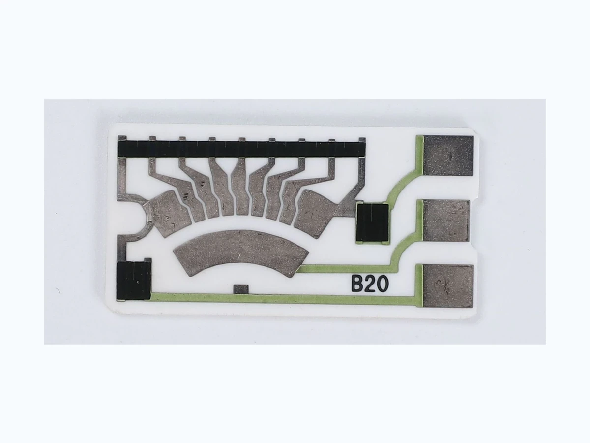
The card drawing should identify the contact path, terminal functions and electrical operating conditions. The sender assembly specification adds float and linkage motion. The receiver specification adds timestamps, raw-data access, electrical tests and diagnostic states. Keeping these interfaces explicit makes it possible to investigate a stationary signal without silently changing the resistance curve to mask an unresolved mechanism.
ChipSimple can review the thick-film card requirements and drawing-defined interfaces. The system integrator owns the fault-detection logic, safe response and validation in the intended liquid-level application. Request a clear record of what independent stimulus must exist before a stuck-float conclusion is permitted; that requirement is often more useful than a more aggressive timeout.
Provide the diagnostic boundaries with the card drawing
The following inputs allow electrical-card requirements to remain separate from system fault assumptions.
- Contact travel, terminal assignment and resistance curve
- Tank geometry and independently observable level-change events
- Receiver electrical test stimulus and normal input loading
- Expected motion interval and permitted diagnostic delay
- As-found traces with raw, filtered and displayed timestamps
The drawing-upload form loads as you reach this section.