
On this page
A stable temperature reading does not prove that an optical emitter, detector or coupling feature remains aligned. The sensor may sit near the heater while the optical reference moves because of differential expansion, asymmetric clamping or a local gradient. A useful validation plan records temperature at physically meaningful points and measures optical or mechanical alignment on the same timeline. It treats mean temperature, spatial nonuniformity and displacement as distinct outputs, then relates them only through an explicit system model.
System boundary
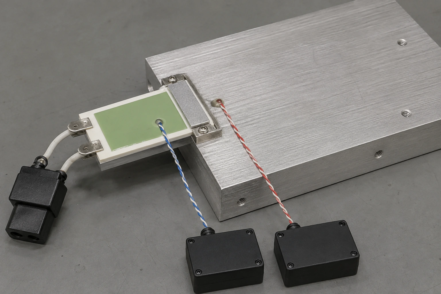
A ceramic thermal platform, its heater and sensing circuit, mounted optoelectronic elements, mechanical constraints, heat sink and alignment references. ChipSimple owns only drawing-defined thick-film manufacture. The device developer owns optical acceptance, control behavior and complete product validation.
System integration decisions
- Name the optical reference features whose relative position matters.
- Place temperature observations at source, interface, sink and alignment-sensitive regions.
- Validate warm-up, regulation and power-transition states separately.
Map heat sources, sinks and optical datums in one assembly view
Show the ceramic platform, printed heater or resistor, optoelectronic die or package, attach layer, housing, clamp, heat sink, temperature sensors and optical axis references. Identify which surface temperature is controlled and which temperatures are inferred. Mark materials and free or constrained expansion directions. The relevant alignment can be emitter-to-fiber, die-to-lens, source-to-detector or two package datums; it must be stated as a relative coordinate. A housing temperature alone cannot represent a junction or adhesive interface without a validated thermal path.
Calculate mean temperature, gradient and displacement as separate metrics
Choose a region of interest and compute its mean only after retaining individual sensor values. Define gradient using specified point pairs or a fitted field. Measure alignment directly where possible. A first-order expansion model can predict displacement but does not replace optical validation.
Δx_pred=Σ_i α_i L_i ΔT_i; G_ab=(T_a-T_b)/d_ab; e_x=x_meas-x_ref
- α_i and L_i describe each material path between optical references.
- ΔT_i is its applicable temperature change, not automatically controller temperature.
- G_ab is a defined temperature gradient between points a and b.
- e_x is measured relative alignment error in the controlled coordinate.
Small deformation and known constraints; adhesive cure, creep and nonlinear contact effects need separate evidence.
Show why equal mean temperature can produce different alignment
Consider an illustrative 20 mm aluminium support referenced to a ceramic feature. If the support's effective expansion relative to the ceramic path is 15 µm/m·K and its representative rise is 18 K, the first-order relative movement is 5.4 µm. In a second condition the same mean sensor temperature is reported, but one end is 6 K warmer because clamping changed; bending or local expansion can add displacement not captured by the mean. These figures explain the sensitivity calculation and are not device tolerances or measured performance.
Place sensors and alignment metrology without perturbing the interface
Select temperature sensors with contact, response and lead routing suited to the point being measured. A large probe can spread heat or alter clamping. Infrared measurements require emissivity and line-of-sight controls. Alignment metrology must resolve the relevant lateral, axial or angular component while avoiding fixture drift. Use reference features outside the heated path to detect bench movement. Synchronize power, temperature, controller output and alignment channels so a transient lag is not mistaken for permanent deformation.
| Channel | Required location or state | Question answered |
|---|---|---|
| Control temperature | At the feedback sensor | What the controller regulates |
| Interface temperatures | Source, sink and critical joints | Where gradients develop |
| Alignment coordinate | Between optical reference features | Whether relative geometry moves |
| Power and time | Warm-up and transitions | Which event drives the response |
Validate warm-up, steady regulation and power changes
Start from a defined soak and record the complete warm-up, not only the final reading. Hold at representative operating powers and ambient boundaries supplied by the device owner. Exercise permitted power steps, standby and restart states. Alignment may peak before temperature settles, and repeated cycles can reveal seating hysteresis. Keep controller tuning fixed during a comparison. If tuning changes, treat it as a new configuration because overshoot and spatial gradients can change even when the same final setpoint is reached.
Distinguish sensor bias, gradient, fixture drift and real movement
A control temperature shift without agreement from nearby references can indicate sensor attachment or calibration. Opposing temperature changes across the platform with stable mean point toward gradient. Alignment movement that also appears in an unheated reference path suggests metrology or fixture drift. Displacement that follows power and reverses during cooling supports a thermal mechanism, while a residual after cooling can involve seating, attach-layer change or creep. These patterns guide follow-up tests but do not by themselves prove root cause.
Budget thermal and alignment uncertainty before comparing limits
Include sensor calibration, attachment, sampling, emissivity where relevant, position of measurement points, alignment instrument calibration, reference stability and repeatability. Propagate temperature uncertainty through any expansion prediction, while keeping direct alignment uncertainty separate. Optical power or coupling can respond nonlinearly to displacement; the device developer owns that conversion and acceptance. Laser or optical radiation, energized heaters and hot surfaces require application-controlled safety procedures. ChipSimple supplies no clinical, optical-output or laser-safety conclusion from a platform temperature test.
Release geometry, thermal boundary and validation ownership together
Provide platform artwork, substrate, heater circuit, attach footprints, mechanical stack, clamp loads, heat-sink condition, sensor locations, optical datums, operating powers and ambient range. Define allowable temperature, gradient, warm-up and alignment outputs separately. Preserve raw data and configuration revisions. ChipSimple can review drawing-defined ceramic thick-film features and electrical heater requirements; the customer controls optical assembly, controller, metrology and product qualification. Reopen the validation after changes to materials, attachments, clamping, sensor, controller, optics or thermal boundary.
Provide the thermal stack and optical reference geometry
A meaningful platform review needs heat-flow conditions and alignment-sensitive datums in the same package.
- Ceramic layout, heater or sensor circuit, materials and attach footprints.
- Power states, controller, sink, ambient and permitted temperature gradients.
- Optical reference features, alignment coordinates and measurement resolution.
- Warm-up, cycling, uncertainty, acceptance and device-validation ownership.
The drawing-upload form loads as you reach this section.