
On this page
Moving a target closer to a heater often seems like an obvious way to increase heating. Directly above the central opening of a ring-shaped emitting surface, that intuition can fail. At a very small gap, the target may see the hot annulus at grazing angles while much of its forward view passes through the hole. A geometric view-factor calculation reveals this effect before gap adjustments are mistaken for changes in heater quality.
System boundary
The analysis covers direct geometric radiation from an annular emitting face to a small coaxial receiving region and its extension to actual sample geometry. It does not establish heater operating limits, emissivity, full enclosure exchange or target temperature.
Integration interfaces
| Interface | Required input | Thick film role | Validation owner |
|---|---|---|---|
| Heater face to receiving region | Emitting radii, temperature distribution, gap and receiver orientation. | Identify the actual drawing-defined visible heater face. | Thermal designer. |
| Radiation path to holder | Aperture walls, clamps, lips and their surface states. | Provide component outline and terminal exclusions. | Mechanical and thermal integration owners. |
| Incident heat to sample response | Sample size, conduction, support and exposure requirement. | Support heater-boundary definition, not final process uniformity. | Process equipment integrator. |
Integration risks
| Risk | Control or verification | Validation owner |
|---|---|---|
| A centre-point factor is treated as whole-sample captured power. | Keep direction, receiving area and spatial averaging explicit. | Thermal analysis reviewer. |
| An aperture blocks the rays assumed by the formula. | Model actual visibility and relevant enclosure surfaces. | Mechanical integration owner. |
| Gap changes are interpreted without measuring heater surface state. | Separate geometry, electrical input and thermal boundary changes. | Thermal validation owner. |
System integration decisions
- Identify the actual emitting annulus rather than the complete ceramic outline.
- Keep the direction and area basis of each view factor explicit.
- Check whether the receiver is small, coaxial, parallel and unobstructed before using the simple formula.
- Separate direct irradiation geometry from reflection, convection and sample temperature.
Define the ring face that is actually visible
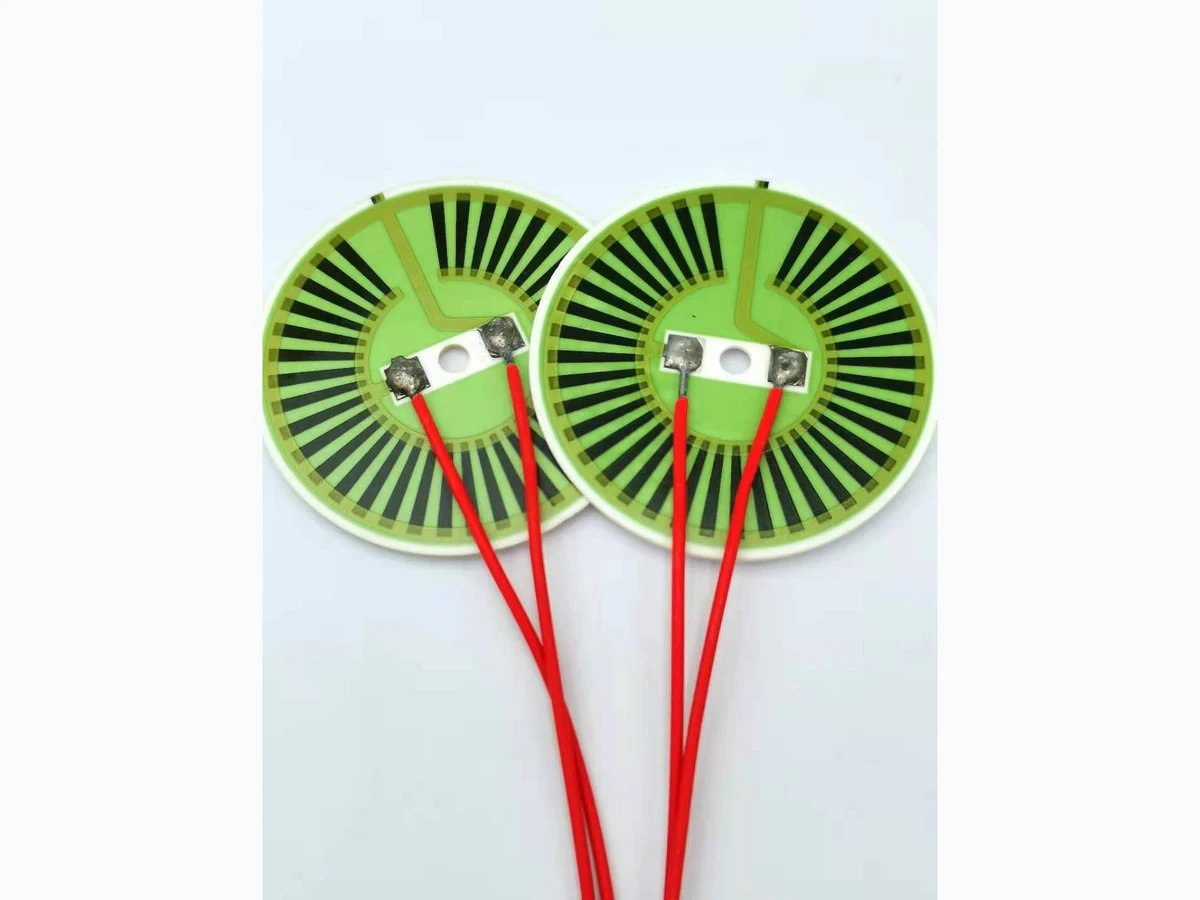
Draw the emitting face, its inner and outer radii, the receiving surface and the perpendicular gap. A ring heater's physical outline need not equal its radiating region: terminals, supports, masking or nonuniform surface temperature may divide the visible face. Record the geometry relevant to the actual radiation path.
The calculation here concerns a very small planar receiving patch on the common axis, parallel to the annulus. It is a local centre-point approximation, not the average over a large workpiece. A curved, offset or tilted receiver needs a different integral. A drawing that specifies only the nearest distance does not establish these conditions.
Keep the view-factor direction explicit
A view factor describes a geometric fraction associated with radiation leaving one diffuse surface and reaching another. Direction matters. The fraction from a small receiver toward a large ring is not numerically the same as the fraction from that ring toward the small receiver. Area reciprocity relates them when the geometry satisfies its assumptions.
For a uniform diffuse ring, the receiver-to-ring factor also weights the ring's direct contribution to irradiation at the receiver. That does not mean the same fraction of the ring's total emitted watts reaches the whole sample. Label the local factor and its receiving patch clearly before putting it in an equipment energy budget.
Subtract the central disk from the outer disk view
For the stated coaxial geometry, integrate the differential view-factor kernel over the annulus. The angle cosines both equal the gap divided by the line-of-sight distance. Integrating around each circular strip gives the outer-disk factor minus the missing inner-disk factor. This subtraction is geometric; it does not require assuming that an imaginary disk physically emits.
Use one length unit for radii and gap. The result is dimensionless and remains between zero and one. It excludes blockage, non-diffuse directional emission and radiation transmitted through other objects. The formula is useful precisely because its small set of assumptions can be checked against the installed drawing.
Freceiver→ring = Ro²/(z² + Ro²) − Ri²/(z² + Ri²)
- Ro and Ri: outer and inner radii of the visible planar annulus
- z: perpendicular distance from its plane to a small coaxial parallel receiver
- Freceiver→ring: direct local view factor from that receiving patch toward the annulus
Differential-size receiver, coaxial parallel planes, positive gap, unobstructed lines of sight and diffuse far-field geometric radiation. This is not the whole ring-to-sample power fraction.
Compare gaps without assuming monotonic improvement
Take hypothetical radii Ri = 10 mm and Ro = 20 mm. At a 5 mm gap, the factor is approximately 0.1412. At 10 mm it rises to 0.3000. At about 14.14 mm it reaches 0.3333, then returns to 0.3000 at 20 mm. For this ideal annulus, the maximum occurs at z = √(Ri Ro). These are geometric example values, not recommended installation dimensions.
At very small gaps above the central hole, the hot ring occupies increasingly grazing directions. At very large gaps, its apparent angular size shrinks. The two effects produce an intermediate maximum. Equal factors at 10 and 20 mm do not imply equal irradiation across a finite sample, equal convection or equal system temperature.
| Gap z | Receiver-to-ring factor | Geometric interpretation |
|---|---|---|
| 5 mm | 0.1412 | Close to the central opening; much of the ring is viewed obliquely |
| 10 mm | 0.3000 | Larger projected annular view |
| 14.14 mm | 0.3333 | Ideal local maximum for these radii |
| 20 mm | 0.3000 | Same centre factor as 10 mm, not the same full-field distribution |
| 40 mm | 0.1412 | Annulus occupies a smaller distant angular field |
Include intervening lips, clamps and aperture walls
A holder lip can block the inner portion of the annulus; a clamp can remove an angular sector; a deep aperture can restrict oblique rays. Those features change the visible integral even if neither heater radius changes. Identify occluded lines of sight from the actual receiving locations rather than applying an arbitrary percentage reduction.
An obstructing surface can itself emit or reflect radiation. Treating it as simply missing heater area may be acceptable only for a stated preliminary direct-path calculation. The complete enclosure can require surface temperatures, optical properties and multiple reflections. Keep the direct view calculation as one named contribution rather than silently extending it into a full radiative model.
Map a finite sample instead of copying the centre value
Points away from the axis see a different portion of the ring and any obstruction. A sample whose diameter approaches the opening or annular width cannot be represented reliably by one centre-point number. Divide it into appropriate receiving regions and evaluate their actual positions and orientations, with refinement sufficient for the decision.
Compare the resulting spatial irradiation pattern with the process requirement. A geometry that maximizes central input can still produce unwanted edge loading or a nonuniform sample temperature. Thermal spreading within the sample, support conduction and exposure time determine the resulting temperature field. The view map identifies an input distribution, not the final thermal result.
Hold surface state separate from geometric view
For a uniform diffuse emitting surface with specified radiosity, direct irradiation scales with the local geometric factor. A real ring can have nonuniform temperature, emissivity or reflected contributions, so integrate the relevant surface output where those differences matter. Visible green glaze does not provide its thermal-radiation properties.
At fixed heater electrical power, changing gap may change the heater temperature and nearby convection as well as geometry. A useful comparison records heater surface state and target conditions rather than attributing every temperature change to view factor. Do not multiply an unrelated two-gray-plane exchange equation by this local factor and assume the enclosure reflection accounting remains valid.
Deliver a gap-and-obstruction map for integration
The design handoff should show the emitting region, receiver positions, gap range, offsets, tilt and all intervening features. State where the differential receiver formula is used and where a finite-area or enclosure model replaces it. Retain the calculated factor independently from any assumed surface emission or measured temperature.
Validate the installed thermal result with appropriate guarded equipment and independent temperature or heat-input evidence. Reopen the geometric review after changing aperture depth, sample size, holder lips, heater orientation or gap adjustment range. The result supports a drawing-specific radiant arrangement; it does not establish product wattage, safe spacing, process uniformity or universal heating performance.
Send the annulus, aperture and receiver geometry
Include the actual line-of-sight boundary rather than a gap value alone.
- Emitting inner and outer boundaries with surface-state information.
- Receiver dimensions, coordinates, tilt and required exposure region.
- Gap range and tolerance, aperture depth and all obstructions.
- Relevant surface temperatures, optical assumptions and electrical input.
- Spatial thermal evidence and the intended uniformity or heating decision.
The drawing-upload form loads as you reach this section.