
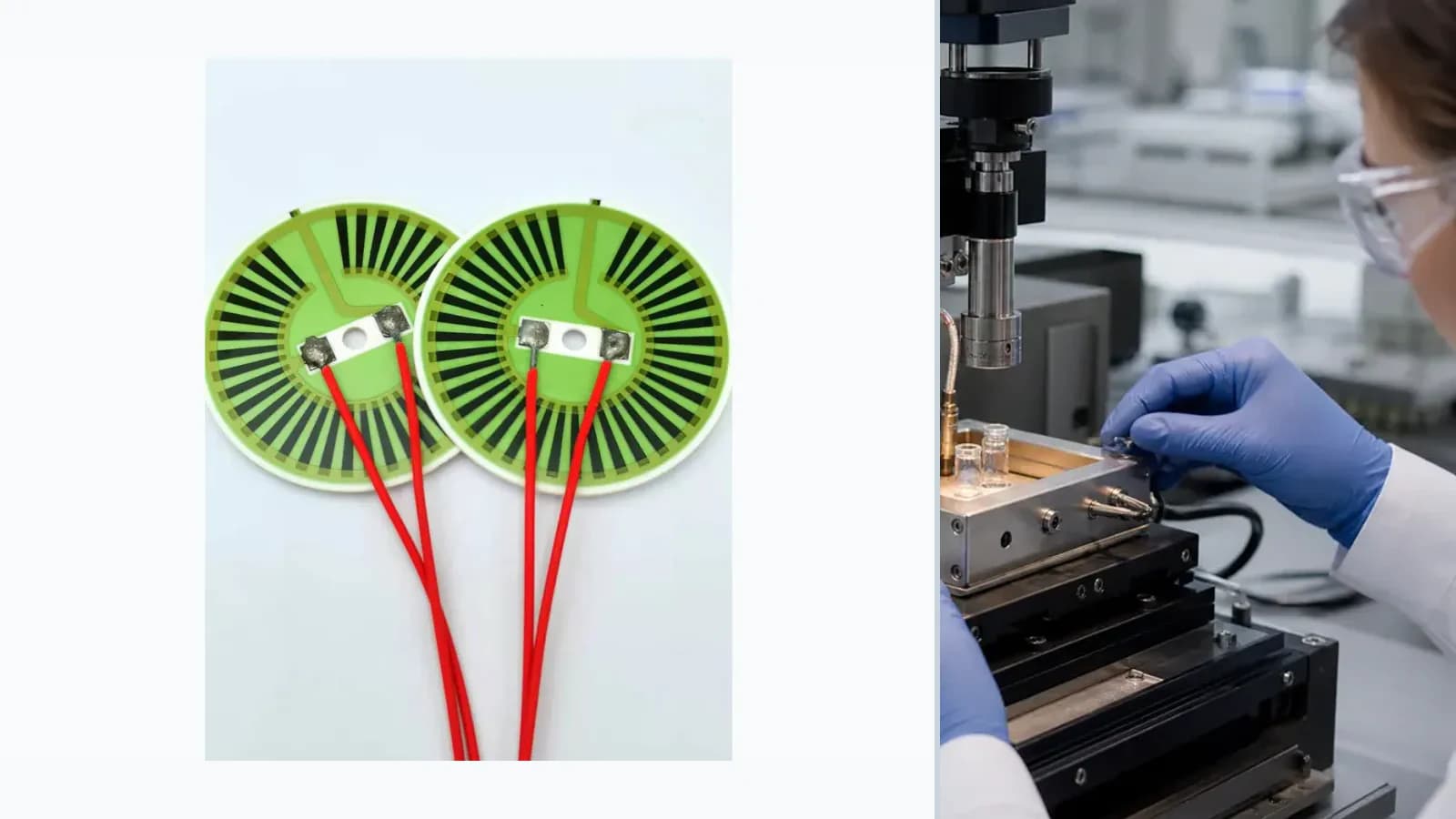
Overview
This application engineering guide maps Sample-Preparation Thick Film Heater Integration as a system-level problem. The printed element is reviewed together with mechanics, electronics, heat flow, media exposure, calibration, failure response, and final-assembly validation.
Failure controls
These are review prompts, not evidence that every risk applies or that every test is available.
- A
Local hot spot at a turn, neck-down, terminal, void, or poor thermal interface
- B
Resistance drift or protection damage after thermal cycling
- C
Dielectric breakdown, leakage, or corrosion under moisture, scale, or contamination
- D
Runaway temperature when flow, contact, sensing, or control is lost
Engineering review matrix
Each row links a design variable to evidence that can support a drawing or release decision.
| Variable | Control question | Verification route |
|---|---|---|
| Electrical target | For Sample-Preparation Thick Film Heater Integration, define voltage, resistance, current, power, duty cycle, and tolerance at the assembly operating point. | Measure cold and operating resistance, current, power, and protective response under the agreed supply condition. |
| Heat path | Substrate, mounting, fluid or air flow, contact resistance, insulation, and ambient determine temperature—not nominal watts alone. | Map temperature at steady state and during transients at relevant boundary conditions. |
| Printed geometry | Trace width, thickness, turns, spacing, neck-downs, and terminal transitions control local current density and heat flux. | Inspect processed geometry and correlate critical regions with the thermal map. |
| Insulation and protection | Working voltage, dielectric stack, creepage, clearance, moisture, scale, and dry-run exposure must be reviewed together. | Use a construction-specific insulation, dielectric, leakage, and environmental plan. |
| Control interface | Sensors, cut-outs, bonding, terminals, control algorithm, and fault state belong to the heater system boundary. | Validate warm-up, overshoot, cycling, sensor response, and defined fault cases in the final assembly. |
System integration route
The order makes assumptions and ownership visible before a result is promoted to a requirement.
- 01
Define the system transfer function
For Sample-Preparation Thick Film Heater Integration, document the functional requirement, operating boundary, interfaces, quantities, and acceptance owner against the current drawing.
- 02
Map mechanical and electrical interfaces
For Sample-Preparation Thick Film Heater Integration, control dimensions, datums, layer stack, interfaces, tolerances, and assembly constraints in the released drawing.
- 03
Set environmental boundaries
For Sample-Preparation Thick Film Heater Integration, complete set environmental boundaries against the controlled drawing, named assumptions, responsible owner, required evidence, and release decision.
- 04
Build the validation matrix
For Sample-Preparation Thick Film Heater Integration, complete build the validation matrix against the controlled drawing, named assumptions, responsible owner, required evidence, and release decision.
- 05
Release assembly-level acceptance
For Sample-Preparation Thick Film Heater Integration, close remaining assumptions and link the quoted or released scope to the drawing revision, evidence set, owner, and change-control plan.
Inputs for a practical review
Unknown values may be labelled unknown. The review should convert uncertainty into an explicit decision or validation task.
Send Drawings- 01
Supply voltage and tolerance; target power or resistance
- 02
Thermal load, mounting stack, medium, flow, ambient, and duty cycle
- 03
Allowed temperature field, warm-up time, and fault limits
- 04
Outline, keep-outs, terminal and sensor interfaces
- 05
Electrical, thermal, cycling, and safety tests