
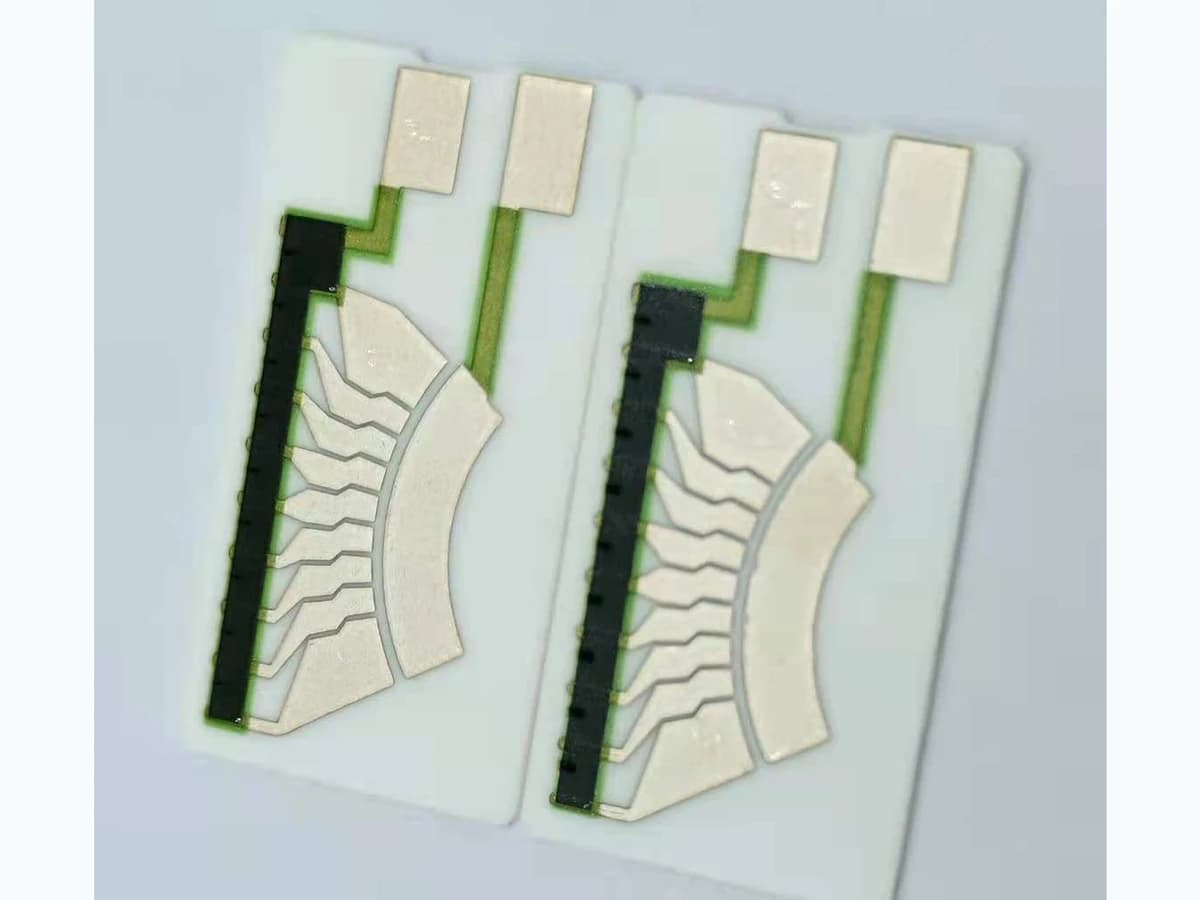
Design question
Which resistance-versus-position law makes the assembled sender meet the required volume indication across tolerance, wear, media, and temperature?
Model the transfer chain before the printed track
| Stage | Input → output | Error sources to expose |
|---|---|---|
| Tank | Volume → liquid height | Tank contour, tilt, baffles, trapped volume, datum |
| Float | Height → float center | Buoyancy, density, immersion, interference |
| Arm and pivot | Float position → angle | Arm geometry, stops, backlash, deformation |
| Wiper | Angle → contact position | Radius, alignment, contact footprint, spring load |
| Resistor card | Position → resistance | Track law, segment geometry, paste, trim, contact resistance |
| Electronics/display | Resistance → indicated level | Pull-up/network, ADC, filtering, software table, damping |
Use a pointwise transfer model before choosing track geometry
Build one controlled row for every required indication point. The symbolic chain Qᵢ → hᵢ → θᵢ → sᵢ → Rᵢ keeps each transformation and its units visible before the printed geometry is selected; Qᵢ denotes the requested fuel volume or percentage point, not electrical voltage.
- Order and version the Qᵢ, hᵢ, θᵢ, sᵢ, and Rᵢ rows; record units, direction, datum, and every assumption.
- Interpolate only with an agreed rule between approved points; preserve intentional reserve zones, dead bands, endpoint behavior, and non-monotonic requirements.
- Convert the nominal sᵢ-to-Rᵢ law into a candidate track or segment layout, then recompute the output with paste, print, contact, mechanism, assembly, media, wear, and temperature tolerances.
- Compare nominal and tolerance-case indicated volume in both travel directions before releasing artwork, calibration data, or display assumptions.
| Symbolic stage | Meaning | Controlled inputs and boundary |
|---|---|---|
| Qᵢ → hᵢ | Required volume or percentage point to liquid height | Tank contour, datum, orientation, baffles, trapped volume, density assumptions |
| hᵢ → θᵢ | Liquid height to float-arm or pivot angle | Float buoyancy, immersion, arm geometry, pivot, stops, interference, direction |
| θᵢ → sᵢ | Mechanism angle to wiper contact position | Wiper radius, alignment, footprint, travel direction, backlash, assembly tolerances |
| Qᵢ → Rᵢ | Required indicated point to nominal sender resistance or electrical output | Gauge or controller circuit, pull-up or network, ADC, software table, endpoints, dead bands |
| sᵢ ↔ Rᵢ | Contact position to the resistor-card target law | Continuous or segmented topology, sheet-count model, conductor taps, contact resistance, trim strategy |
Use one controlled data table
- Mechanical datum and coordinate system
- Volume or percentage points with corresponding liquid height
- Float and arm position or angle at each point
- Wiper contact coordinate and direction of travel
- Required nominal resistance/output at each point
- Allowed error, hysteresis, dead bands, end stops, and display logic
- Temperature, media, orientation and tolerance cases represented
Convert the target law into manufacturable geometry
The layout may use a continuously varying track, discrete printed segments, conductor taps, or a combined strategy. Each approach changes local sheet count, current distribution, contact transitions, trim options and tolerance sensitivity. Keep the wiper footprint, gaps, conductor overlaps and end zones visible in the model.
Nominal geometry is only one contributor. Paste variation, print and firing movement, contact resistance, arm and wiper tolerances, assembly alignment and media/wear effects need a tolerance analysis tied to the required system output.
Validate direction, not only endpoints
- Check empty/full and intermediate points in both travel directions
- Separate sender resistance from harness and electronics behavior
- Measure repeatability, hysteresis, contact transitions and open-circuit behavior
- Exercise tolerance builds, temperature and relevant wetted-media conditions
- Define calibration, sampling, wear/endurance and disposition records
- Release the curve table, drawing revision, test method and software/display assumptions together
- Keep ignition-risk assessment, sealing, fuel compatibility, applicable regulation, and complete-sender safety approval with the OEM or complete-system owner
Budget curve error by transfer stage and tank region
Linearization should be reviewed point by point, not as one headline accuracy number. Build nominal, minimum, and maximum cases for each required volume point and for both rising and falling travel. Keep manufacturing variation, mechanical hysteresis, contact behavior, electronics conversion, environmental effects, and test uncertainty in separate columns so the team can see whether artwork, calibration, mechanism, software, or the validation method owns the dominant contribution.
Use additional points where tank contour, baffles, float interference, linkage ratio, segmented track transitions, reserve indication, or endpoint geometry changes quickly. A sparse table can look acceptable at empty, half, and full while missing the region that matters to warning logic or customer perception. The OEM should define the volume datum, interpolation rule, acceptance denominator, and treatment of inaccessible or intentionally damped regions.
| Contributor | Question for every required point | Verification and owner |
|---|---|---|
| Tank and fill reference | How do contour, orientation, baffles, trapped volume, thermal expansion, fill method, and datum move liquid height for the stated volume? | OEM tank model and controlled-volume correlation, including test uncertainty and representative installation attitudes |
| Float, arm, pivot, and stops | How do density, immersion, linkage ratio, backlash, compliance, friction, interference, tolerances, and travel direction move the contact position? | Mechanism owner records true position during forward and reverse sweeps with tolerance builds and relevant fluids |
| Wiper and printed path | How do alignment, footprint, normal load, track law, segment boundaries, conductor taps, printed variation, trim, contact resistance, and wear alter resistance? | Component and sender owners correlate actual contact position with measured output using the released mating interface |
| Harness and electronics | How do lead resistance, excitation, input impedance, ADC conversion, filtering, diagnostics, lookup tables, damping, and software revision change the indicated result? | System owner replays raw sender values and measured assemblies through the documented electrical and software chain |
| Environment and service state | How do temperature, named fuel, additives, contamination, slosh, vibration, dwell, aging, and storage affect mechanics, contact, resistance, and interpretation? | Qualified validation owner applies the agreed sequence and repeats the same pointwise correlation before and after exposure |
| Acceptance and measurement | Which reference, direction, stabilization, sampling, repeatability, uncertainty, guard band, and disposition rule determine pass or fail? | Released validation plan assigns the instrument, fixture, sample, calculation, reviewer, and decision authority |
Release the curve as a controlled system package
- Tank drawing or volume-height table with datum, installation attitude, baffles, reserve region, and revision
- Float, arm, pivot, stops, wiper radius, contact footprint, clearances, tolerance stack, and both travel directions
- Ordered Qᵢ, hᵢ, θᵢ, sᵢ, and Rᵢ table with units, interpolation, endpoints, dead bands, and assumptions
- Resistor-card artwork, substrate and functional materials, printed topology, conductor taps, trim, protection, and inspection state
- Mating wiper identity, contact load, speed, cycling, vibration, interruption, wear, and acceptable surface-change criteria
- Excitation, harness, connector, input impedance, filtering, conversion, diagnostics, display or software table, and revision
- Named fuel and additive range, temperature, contamination, slosh, storage, environmental sequence, and exposure ownership
- Nominal and tolerance-case pointwise results in both directions, including measurement uncertainty and guard-band decision
- Prototype quantities, fixture, calibration references, sampling, fault injection, acceptance criteria, records, and deviation route
- Responsibility split for component manufacture, sender assembly, sealing, ignition risk, vehicle integration, regulation, and final approval