
On this page
- Translate Tank Geometry into an Electrical Curve
- Design Segment and Resistor Geometry Together
- Qualify the Sliding Contact System
- Protect Against Fuel and Contamination
- Control Calibration and Traceability
- A Worked Engineering Review
- Design Review Checklist
- Questions Engineers Commonly Ask
- Related Engineering Resources
- Closing Note
Prepared by Chipsimple Engineering Team, Engineering and technical content review
Published online August 10, 2026 · Reviewed August 10, 2026
ENGINEERING ARTICLE 28 / VOLUME 5
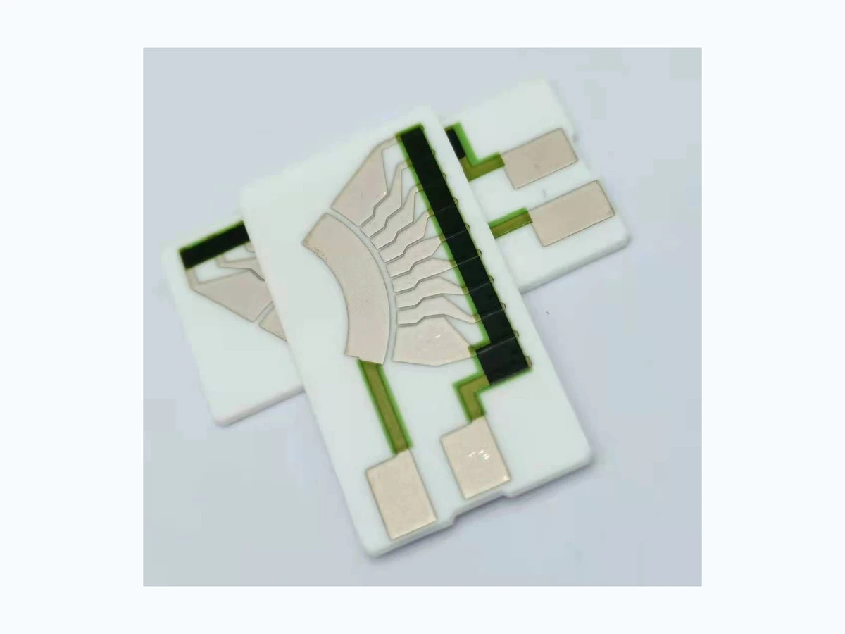
Engineering a Fuel-Level Sensor Resistor Card for Stable Wiper Contact
The card is more than a printed resistor. A moving contact travels across segments or a continuous path, and the electrical output depends on resistor values, segment geometry, wiper force and contact resistance. Fuel chemistry, vibration and particles influence the sliding interface. The mechanical pivot and float geometry then translate liquid level into contact position.

Translate Tank Geometry into an Electrical Curve
In a stable manufacturing route, liquid volume is rarely linear with float angle. This means equal angular steps may not represent equal volume or gauge indication. The observation is especially useful because it connects a visible feature to an electrical, thermal or mechanical consequence.
The control plan should define the target resistance-versus-angle or volume table. It should also name the drawing characteristic or coupon that represents the requirement, avoiding an instruction that depends on personal interpretation.
Evidence comes from calibration at controlled mechanical positions. A trend across position or lot is usually more valuable than a perfect reading from one hand-picked sample.
Investigate a precise resistor network producing an inaccurate fuel indication. The pattern may identify a narrow process interaction long before the final circuit becomes an open, short or out-of-tolerance value.
Design Segment and Resistor Geometry Together
A useful way to frame the decision is this: Wiper position, contact width and printed resistor network determine step size and continuity. As a result, narrow gaps can bridge while wide gaps create signal dropout. That cause-and-effect chain should remain visible when fuel level sensor resistor card is reviewed with purchasing and quality teams.
The manufacturing boundary is protected when the team can coordinate segment pitch, wiper footprint, registration and resistance values. This approach separates the customer's functional need from the supplier's machine-specific compensation.
Confirm the decision with contact sweep data and magnified geometry inspection. Include both typical and boundary-condition specimens where the failure consequence justifies them.
The symptom intermittent output at transitions despite correct static resistors deserves a structured investigation. Check material lot, artwork position, thermal history and measurement setup before assigning a single cause.
Qualify the Sliding Contact System
Geometry and material meet at this point: Contact metallurgy, force, surface roughness and fuel film control resistance and wear. Therefore, high force may improve initial contact but accelerate wear. A nominal specification that omits the interface is incomplete even if every individual value looks reasonable.
During release, specify wiper material, force range, path and surface construction. Make sure the acceptance method measures the same physical feature that the design calculation assumed.
Useful confirmation includes contact-resistance noise and endurance cycling in representative fuel. Keep photographs or sections tied to part, revision, lot and orientation so they remain evidence rather than decoration.
One failure signature is stable bench readings followed by noisy field output. It often becomes clear only when results are sorted by position, process stage or exposure instead of being combined into one average.
Protect Against Fuel and Contamination
Process capability follows from the mechanism: Fuel composition, additives, water and debris can alter surfaces. The direct implication is that corrosion, deposits and particles affect both resistor and contact tracks. This makes the topic a design input, not merely a factory setting adjusted after the drawing is complete.
A practical release action is to define fuel families, temperature and contamination exposure. The requirement should survive staff changes and future lot reviews because it is recorded with the controlled construction.
Use immersion, biased exposure and post-test sweep to demonstrate margin. When feasible, compare the result before and after the operation most likely to disturb it.
Pay attention to material compatibility inferred from dry-air cycling. A corrective action is credible only when it changes that physical mechanism and the follow-up data confirm the change.
Control Calibration and Traceability
Final output combines printed values, trim, mechanical assembly and wiper position. The consequence is that testing only the bare card cannot prove assembled calibration. In a fuel level sensor resistor card review, this relationship deserves an explicit decision rather than an assumption copied from a previous drawing.
The practical control is to set card-level and assembly-level test points and tolerances. That instruction should be linked to the layer, material system or feature it governs so that production and inspection read it in the same way.
Verification should include serialized calibration curves and endpoint checks. If the evidence is collected only after final assembly, the team loses the ability to separate printing, firing, trimming and assembly effects.
A common warning sign is good component data with gauge error caused by assembly stack-up. Treat that symptom as a request to examine the process chain, not simply as a reason to widen the final tolerance.
A Worked Engineering Review
A tank requires a nonlinear output table. The designer converts volume to float angle, then allocates resistor values and segment positions. Critical transition gaps are checked against wiper width and registration. Printed resistors are trimmed at card level, but final calibration includes pivot and float-arm tolerances. Endurance testing sweeps the wiper through representative fuel while monitoring contact noise and total resistance. Wear inspection confirms whether the contact force and track metallurgy remain balanced.
Design Review Checklist
- Provide volume-angle-resistance table.
- Coordinate segment pitch and wiper footprint.
- Specify contact material and force.
- Test in representative fuel and contamination.
- Calibrate the assembled mechanism.
Questions Engineers Commonly Ask
Why can a card pass resistance test but fail in a sensor?
Bare-card resistance does not include wiper contact, mechanical position, vibration or fuel effects.
Should the output be linear?
Only if the tank and gauge system require it. Many tanks need a tailored nonlinear curve.
What is the key wear test?
A representative wiper, force, fuel, temperature and cycle profile while monitoring contact resistance and noise.
Related Engineering Resources
Closing Note
Fuel-level card performance is a mechatronic result. Treat the printed network, sliding contact, tank geometry and calibration record as one controlled sensor system.