
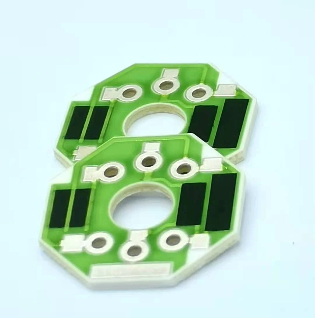
On this page
A ceramic via can have the correct reported center and still leave too little metal land on one side if the hole is oval or locally enlarged. The opposite can also occur: a round hole shifted within a larger pad may have a location error without the same minimum-land result as an oval hole. Inspect the hole contour, pad contour and their relationship before reducing the result to one annular-margin number.
Measurement purpose
Determine minimum planar metal land while preserving actual hole shape and displacement.
Specimens and conditions
- Boundary identity
- Face, entrance/chamfer and metal contour explicitly distinguished.
- Relative geometry
- Hole and pad remain in one controlled coordinate system.
Equipment and records required
- Capture: Resolved boundaries with documented scale and illumination.
- Contour analysis: Actual edge coordinates, fitted-shape residuals and local distance mapping.
Method sequence
- Identify
Locate the controlled hole and metal boundaries.
Record: Face and boundary map.
- Measure
Separate ovality, center offset and contour residuals.
Record: Shape and displacement data.
- Evaluate
Find the critical local land without substituting average diameter.
Record: Minimum location and method limitation.
Decision and uncertainty
Use actual relevant contours for the drawing-defined planar land decision.
Edge resolution and registration affect the result; planar land does not prove buried continuity.
Drawing and dimensional inspection owners.
Traceable outputs
| Record | Required contents |
|---|---|
| Contour report | Original image, boundaries, shape fit and displacement. |
| Land map | Governing points, minimum distance and unresolved integrity questions. |
Method review decisions
- Keep hole shape, hole position and pad shape as separate observations.
- Use actual contours for the critical land rather than subtracting an average hole radius.
- Do not infer through-hole metallization continuity or ceramic strength from a top-surface land measurement.
Identify which surface and boundary the drawing controls
State the inspected face and whether the boundary is the hole entrance, a chamfer, the cylindrical passage or a metallization edge. A top image can show a broad chamfer that does not represent the minimum through-hole opening. Conversely, a pin that fits the passage does not measure the outside contour of the entry land. Match the observation to the actual drawing feature.
Define the pad boundary that surrounds that opening. The visible metal may include a designed recess, an irregular printed edge or an overglaze window that is smaller than the underlying pad. Do not measure land to the glass edge when the requirement concerns metal remaining around the hole. Separate pad geometry from the protective-glass coverage requirement and preserve both layer identities in the inspection record.
Capture the hole and pad in the same coordinate system
Use an image or measurement setup that preserves their relative position. Record the specimen face, focus plane, scale and orientation. If separate captures are required, register them using stable surrounding features and report the alignment residual. Fitting each feature independently to the center of its own image would erase the offset the inspection needs to detect.
Check whether the relevant edges are resolved and have sufficient contrast. A nominal pixel scale does not establish optical resolution or edge accuracy, and reflections from metal can alter apparent boundaries. Preserve authentic source data and inspect the edge overlays. Validate the capture for the ceramic, conductor finish and surface geometry actually being measured, not only for a calibration pattern.
Separate an oval hole from a displaced round hole
For a fitted ellipse, record its major and minor semiaxes, orientation and fitted center. Also inspect the residual contour deviations. A least-squares ellipse can summarize overall ovality while smoothing over a local breakout or notch. Keep the actual boundary points available where a minimum margin depends on that local feature.
Measure the hole-center displacement relative to the relevant pad datum separately. Do not assume the hole's fitted center, the pad's fitted center and the drawing datum are interchangeable. State how each was determined. An irregular pad may not have one meaningful center for every inspection purpose; in that situation the contour relationship is more useful than a center-to-center offset alone.
Work a centered oval-hole example
Consider a hypothetical circular metal pad with radius 1.50 mm. Inside it is a centered elliptical hole with major semiaxis 1.10 mm and minor semiaxis 0.90 mm. The narrowest planar land is along the major-axis ends: 1.50 minus 1.10 equals 0.40 mm. Along the minor axis the land is 0.60 mm. These are geometric examples, not proposed ceramic via dimensions or acceptance limits.
If the hole is replaced in the calculation by an average radius of 1.00 mm, the reported land becomes 0.50 mm and misses the true minimum by 0.10 mm. Correct center location does not solve that error. The issue is the lost shape information. Retain both axes and the critical contour instead of presenting the averaged diameter as though it represented the worst direction.
| Hypothetical geometry | Minimum land | Interpretation |
|---|---|---|
| Centered ellipse, semiaxes 1.10 and 0.90 mm, pad radius 1.50 mm | 0.40 mm | Major-axis ends govern |
| Same hole replaced by average radius 1.00 mm | Calculated 0.50 mm | Averaging hides the narrow side |
| Same ellipse offset 0.20 mm along its major axis | 0.20 mm | Shape and offset act in the same direction |
| Offset at another angle | Evaluate actual contours | The aligned-axis result is not generally exact |
Add displacement without hiding its direction
Move the example ellipse center by 0.20 mm along its major axis while keeping the circular pad fixed. The farthest hole point is now 1.30 mm from the pad center, so the minimum land is 1.50 minus 1.30, or 0.20 mm. Reporting only the original ovality or only the center displacement would omit part of the result.
For an arbitrary displacement direction, subtracting the major semiaxis and displacement magnitude from the circular pad radius gives a conservative lower bound while the hole remains inside the pad. It is not always the exact minimum because the major-axis end may not align with the displacement. Use the measured contour to obtain the actual result. A negative calculated bound alone does not prove contour overlap when that bound is conservative.
Calculate the actual narrow side for noncircular pads
Where both boundaries are irregular, determine the shortest in-plane distance between the actual hole boundary and the enclosing outer metal boundary, under the drawing's definition of remaining land. Confirm first that the hole lies within the intended metal region and that the surrounding land is connected. If a metal discontinuity intersects the land, a simple positive outer-boundary distance can overlook the break.
Keep a location map of the governing points rather than only the minimum number. Inspect whether an isolated edge pixel, unresolved highlight or real notch produces that result. Do not delete an inconvenient local minimum automatically as noise. Apply a justified image-quality or contour-processing rule consistently and retain the unprocessed evidence for comparison with the physical feature.
Keep planar margin separate from via integrity
A continuous-looking top land does not prove metal coverage through the hole, connection to another layer, or the absence of a buried crack. Use electrical access and an appropriate additional observation when the acceptance question concerns those features. Do not substitute a top-view dimensional report for a continuity, section or other construction-specific verification requirement.
Likewise, this margin is not a ceramic strength or fracture calculation. Hole-edge damage, substrate thickness, loading and machining history can matter mechanically even when the metal land is adequate. Keep those decisions with their respective requirements. A drawing may control several independent features at the same via; passing one does not authorize reporting all of them as conforming.
Report the contours and the governing location
The inspection record should include face, boundary definitions, raw capture, scale, fitted shape parameters, displacement vector and local margin map. Identify the minimum location and its edge-quality limitation. Separate dimensional uncertainty from real variation between specimens. When measurements cannot resolve the required margin, improve the method or select a complementary observation before assigning acceptance.
For a ceramic substrate or metallized-via enquiry, provide the drawing and the exact land requirement along with actual hole and pad images. ChipSimple can review construction-specific geometry and inspection access by drawing. The deliverable is an interpretable contour relationship that preserves ovality and offset, not a universal via-size rule or a claim that every visible annulus establishes complete via reliability.
Define the via land requirement
Send the relevant face geometry and separate the dimensional requirement from electrical or structural checks.
- Ceramic drawing with hole, pad, chamfer and overglaze definitions.
- Authentic face images with scale and inspection setup.
- Hole shape, pad contour and coordinate datum information.
- Planar land acceptance rule and any separate via continuity requirements.
The drawing-upload form loads as you reach this section.