
On this page
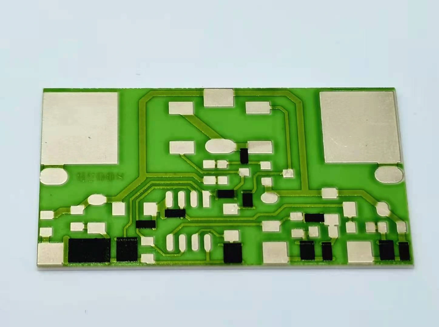
A bright patch on a glossy green overglaze can look like exposed ceramic, while a shadow beside a raised conductor can resemble an open trace. Neither appearance identifies missing material by itself. The useful question is whether the indication stays attached to the same physical boundary when illumination changes. A controlled comparison separates image formation from product condition and tells the inspector when optical evidence is insufficient for a disposition.
Measurement purpose
Classify illumination-dependent indications on glossy printed ceramic surfaces.
Specimens and conditions
- Surface state
- As-found, identified layer and unchanged suspect region.
- Location
- Stable landmarks outside the indication.
Equipment and records required
- Imaging: Recorded native scale, focus and exposure with controllable illumination.
- Confirmation: Method selected for the actual material-continuity question.
Method sequence
- Capture
Record opposite-light and optional polarized views.
Record: Original images and settings.
- Compare
Separate moving intensity from persistent boundaries.
Record: Registration residual and interpretation.
- Confirm material
Resolve persistent indications with a suitable independent observation before assigning continuity.
Record: Confirmation method, location and remaining limitation.
Decision and uncertainty
Do not accept or reject material continuity from glare alone.
Include optical resolution and alignment limitations.
Drawing and inspection acceptance owner.
Traceable outputs
| Record | Required contents |
|---|---|
| Indication report | Coordinates, image pair, optical explanation and confirmation status. |
| Acquisition record | Native files, scale, focus, illumination, exposure and registration residual. |
Method review decisions
- Keep the specimen and image coordinates fixed while changing one lighting variable.
- Retain unsaturated source images, including views that contradict the initial interpretation.
- Escalate unresolved material continuity to a suitable independent method rather than retouching the image.
Identify the material boundary being judged
Mark the suspect region on the drawing before choosing a light. Is the question continuity of a printed conductor, coverage of protective glass, or a chip in the ceramic itself? Those boundaries can overlap in a top view. A transparent or partly translucent glass layer may show underlying metal, and a pad window may intentionally expose a different surface. Compare with the correct layer artwork rather than treating every color transition as an edge.
Give the region a stable identifier and record its distance from two recognizable features. Include one unaffected neighboring area with the same material and orientation. It is a comparison surface, not a certified defect standard. Do not clean, scratch or touch the indication before its initial appearance has been captured; preparation can remove the very feature that needs explanation.
Lock capture settings before comparing appearances
Keep magnification, focus plane, specimen position, exposure, gain and image processing recorded. Disable automatic adjustments where the equipment permits a controlled comparison. An automatic exposure change can make the second image appear more uniform simply by suppressing bright detail. Save native-resolution files, not only a screenshot from a viewer with unknown resizing or sharpening.
Check the intensity distribution at the suspect area. If highlights are clipped at the sensor maximum, different surfaces may share the same recorded value. Lower the exposure enough to recover information and repeat the view. An image that is comfortably visible on a monitor can still contain saturated pixels. The objective is usable contrast at the material boundary, not a brighter or more attractive photograph.
Reverse the light direction without moving the part
Acquire an oblique-light view from one side and a second view from the opposite side at comparable incidence. A shadow from a raised edge should change its direction relative to the edge. A specular highlight can move or disappear as the source leaves the reflecting geometry. An actual missing region remains at the same material coordinates, although its brightness can also change.
That distinction prevents an overly simple rule that a changing image always means a harmless reflection. A real defect can be most visible under only one light. Compare the location and shape of its physical boundary, not just its average brightness. Keep both views and ask which observation would separate exposed ceramic from intact glass. If no available view resolves that distinction, record an unresolved indication and select another method.
Use polarization as a comparison, not an eraser
A polarizer at the source and an analyzer in the imaging path can suppress some reflected glare when their axes are appropriately arranged. Capture the unpolarized and polarized conditions with their settings identified. Because filters reduce available light, exposure may need to change; record that change instead of comparing pixel values as though illumination were identical.
Different surfaces do not respond identically to polarization. Metallic conductors, glass and ceramic can retain different reflected components, and geometry matters. A darkened highlight is evidence that the optical arrangement changed, not proof that the underlying material is sound. Use the polarized view to reveal boundaries obscured by glare, then verify that the apparent edge remains consistent with the other views and the layer construction.
Work a registered-image comparison
Assume a hypothetical inspection image has a measured scale of 5 micrometers per pixel. A suspicious bright region extends 12 pixels from a pad edge under left-side light, but only 3 pixels under right-side light. The apparent extent changes from 60 to 15 micrometers. That 45 micrometer change is a lighting response, not a measured loss of 45 micrometers of material.
Suppose a separate two-dimensional boundary remains 4 pixels from the same pad edge in both views. Its repeated position corresponds to 20 micrometers at the stated scale, but that still does not prove which material forms the boundary or that the optics can measure it accurately. Inspect focus, registration residual and contrast, then compare with another physical observation. The example demonstrates how to separate an image-dependent extent from a persistent feature without declaring either acceptable.
| Observation | What it establishes | Next check |
|---|---|---|
| Bright region moves when light reverses | A strong illumination-dependent component exists | Inspect the underlying boundary in a nonsaturated view |
| Dark stripe changes sides of a raised edge | A shadow is contributing to appearance | Compare topography and opposite illumination |
| Boundary remains fixed across views | A repeatable spatial feature exists | Identify material and determine whether continuity is affected |
| Polarization reveals a previously hidden edge | Glare had obscured information | Confirm edge location against an independent view |
| No view resolves the suspect region | Optical evidence is insufficient | Select appropriate electrical or surface metrology |
Separate image registration from apparent feature movement
Use nearby stable landmarks to confirm that the images represent the same specimen position. If the camera or part moves between captures, align the views using features outside the suspect region. Do not fit the alignment to the indication itself, because that can force a moving highlight to appear stationary. Preserve the original images alongside any registered comparison.
Small perspective or focus changes can shift apparent edges. Check more than one landmark and report the residual alignment error in the same units used for the feature. A feature movement comparable to that residual is not resolved by the comparison. When the part has substantial topography, one planar transform may not align every height correctly; inspect the region at its actual working plane.
Choose confirmation that answers the material question
For a possible conductor interruption, a suitable low-stress continuity measurement may test an accessible path, but parallel branches can hide an open. For possible glass loss, a surface profile or appropriately planned section may distinguish a recess from a color change. Neither a normal resistance reading nor a smooth-looking photograph proves every protective layer remains intact.
Choose the least disruptive useful observation first. Record which later operations could remove residue, alter contact, or destroy the surface. Destructive analysis needs specimen authorization and a section location tied to the original coordinates. Do not select a visually dramatic spot after the electrical evidence has implicated a different location. The final conclusion should name the evidence actually supporting material loss, not merely the most convincing image.
Deliver an image pair that another inspector can reproduce
The report should identify the circuit, revision, layer, region, light directions, exposure, polarization, focus and native image scale. Include the full context view and the local registered pair. Mark the interpretation as confirmed material condition, identified optical artifact or unresolved indication, with the specific follow-up that supports that classification.
For a ceramic thick film manufacturing enquiry, supply representative acceptable and suspect images together with the drawing-defined acceptance feature. ChipSimple can review the circuit construction and inspection requirement by drawing. This comparison does not establish a universal minimum defect size or promise that every glossy surface can be classified optically. Its value is a reproducible decision trail that avoids both false rejection from glare and false acceptance from an attractive image.
Send the suspect surface and acceptance feature
Provide the original image pair and the layer construction so the physical question can be reviewed.
- Circuit drawing and the conductor, glass or ceramic boundary being accepted.
- Native images under the recorded illumination, exposure and polarization settings.
- Known image scale, focus plane, stable landmarks and observed registration residual.
- As-found handling history and any electrical or surface measurements already performed.
The drawing-upload form loads as you reach this section.