
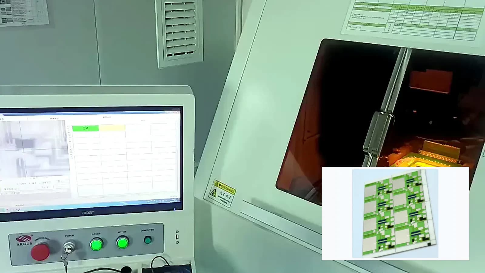
Overview
This quality method record defines Laser Trim Verification and Release through purpose, specimen condition, equipment or method, sequence, acceptance logic, and traceable output. Equipment presence alone is not proof of tolerance, range, accreditation, or released capability.
Measurement route
The order makes assumptions and ownership visible before a result is promoted to a requirement.
- 01
Translate the drawing requirement
For Laser Trim Verification and Release, control dimensions, datums, layer stack, interfaces, tolerances, and assembly constraints in the released drawing.
- 02
Condition and identify specimens
For Laser Trim Verification and Release, document the functional requirement, operating boundary, interfaces, quantities, and acceptance owner against the current drawing.
- 03
Verify method and equipment status
For Laser Trim Verification and Release, agree the inspection method, sample plan, acceptance criteria, traceability, and report format before validation.
- 04
Capture result and uncertainty
For Laser Trim Verification and Release, document the functional requirement, operating boundary, interfaces, quantities, and acceptance owner against the current drawing.
- 05
Link disposition to lot and revision
For Laser Trim Verification and Release, complete link disposition to lot and revision against the controlled drawing, named assumptions, responsible owner, required evidence, and release decision.
Engineering review matrix
Each row links a design variable to evidence that can support a drawing or release decision.
| Variable | Control question | Verification route |
|---|---|---|
| Functional objective | For Laser Trim Verification and Release, value adjustment, hole creation, separation, or marking use different beam, geometry, and acceptance logic. | Release the operation only against a named drawing feature or measured target. |
| Energy interaction | Wavelength, pulse, energy, focus, speed, repetition, assist, and material absorption control removal and thermal damage. | Establish a process window on representative stacks and monitor critical parameters. |
| Geometry | Kerf, taper, recast, debris, radius, path, trim shape, and distance to conductors or edges influence function. | Inspect the processed feature using its drawing datum and suitable method. |
| Measurement loop | For trimming, probe condition, settling, increments, algorithm, overshoot margin, and final verification form a closed loop. | Record initial, target, final, and stability values with program and lot identity. |
| Post-process integrity | Cleaning, microcracks, heat-affected regions, insulation, strength, and assembly must remain acceptable. | Use visual, dimensional, electrical, and reliability checks selected for actual risk. |
Failure controls
These are review prompts, not evidence that every risk applies or that every test is available.
- A
Overcut, overshoot, taper, or geometry outside tolerance
- B
Recast, debris, carbonization, microcracking, or heat-affected damage
- C
Electrical instability from trim geometry or inadequate post-trim margin
- D
Registration loss between program, datum, artwork, and revision
Inputs for a practical review
Unknown values may be labelled unknown. The review should convert uncertainty into an explicit decision or validation task.
Send Drawings- 01
Feature or electrical target and drawing datum
- 02
Material stack and laser-access constraints
- 03
Geometry, edge quality, damage, and cleanliness acceptance
- 04
Measurement and program control for closed-loop trimming
- 05
Post-process electrical, mechanical, and reliability checks