
On this page
Two angle readings of 359 degrees and 1 degree can describe positions close to the same zero direction. Their ordinary average is 180 degrees, which points the other way. This is a coordinate problem, not necessarily a defective resistor card. Before averaging liquid-level sender or rotary position inspection data, determine whether the angle represents a repeating direction, a limited mechanical travel or accumulated rotation. Those quantities require different arithmetic.
Measurement purpose
Prevent angular wrapping and averaging artifacts in rotary resistive-sensor inspection.
Specimens and conditions
- Mechanical coordinate
- Defined datum, positive sense, stops and valid travel branch.
- Electrical state
- Known output-to-angle calibration and matched reference observations.
Equipment and records required
- Independent angle reference: Known display wrap, accuracy and relation to actual contact motion.
- Acquisition and calculation: Preserve paired raw values and a tested degree/radian/modulo convention.
Method sequence
- Define
Classify direction, limited travel or accumulated turns.
Record: Coordinate and branch contract.
- Calculate
Form paired errors and use the appropriate mean.
Record: Raw pairs, signed residuals and concentration when relevant.
- Challenge
Test seam, antipodal and missing-path cases.
Record: Implementation tests and ambiguous-result policy.
Decision and uncertainty
Accept the arithmetic only when it preserves the physical coordinate and exposes ambiguous states.
Circular concentration does not replace reference or inverse-calibration uncertainty.
Sensor calibration and fixture owners.
Traceable outputs
| Record | Required contents |
|---|---|
| Angle-error data | Raw pairs, convention, branch and unrounded residuals. |
| Calculation verification | Boundary tests, concentration rule and indeterminate cases. |
Method review decisions
- Use circular differences only when directions separated by a full revolution are physically equivalent for the decision.
- Preserve unwrapped travel and mechanical stop identity when turns or travel branches matter.
- Report concentration with a circular mean; opposite directions do not define a useful average direction.
Decide whether the angle is a direction or a travel coordinate
A shaft orientation can be reported modulo one revolution. In that representation, zero and 360 degrees denote the same direction. A float arm constrained by stops may instead have a permitted travel interval that happens to cross the instrument's display seam. Its position must remain on that known physical branch. An accumulated encoder count has another meaning again: one turn cannot simply be discarded when total movement is required.
Write the coordinate definition beside the inspection data. State the positive rotation direction, datum and permitted travel. Do not use a tank-level percentage as though it were an angle; the installed arm and tank geometry determine that conversion. First obtain the physical angle that the electrical calibration is intended to represent, then choose the arithmetic suitable for that coordinate.
Calculate the shortest signed directional difference explicitly
For equivalent directions, subtract the reference angle from the observed angle and wrap the difference into a declared interval. One convenient convention is minus 180 degrees inclusive to plus 180 degrees exclusive. An observation of 1 degree against a reference of 359 degrees then has a signed error of plus 2 degrees, not minus 358 degrees. Reversing the two readings gives minus 2 degrees.
The exactly opposite direction is special: plus and minus 180 describe equally short routes. The chosen interval returns minus 180, but that is a numerical convention rather than evidence of which way the mechanism traveled. Preserve the original readings and identify this ambiguity. A shortest-path difference must not be used to hide a full extra turn or an excursion beyond an end stop.
e = mod(theta_observed − theta_reference + 180, 360) − 180
- theta_observed and theta_reference: directions in degrees using the same datum and positive sense.
- mod(a,360): nonnegative mathematical remainder in [0,360), not an implementation-dependent signed remainder.
- e: signed shortest directional difference in [-180,180) degrees.
The physical decision identifies angles differing by a complete revolution. Turn count, prohibited motion and limited-travel branch identity are evaluated separately.
Average unit vectors instead of displayed degree numbers
Convert each direction to a unit vector. Average its cosine components and its sine components separately, then use the two-argument arctangent of those averages to obtain the mean direction. The vector construction recognizes that the ends of the displayed angular interval join. Convert degrees to radians before calling trigonometric functions that expect radians.
Let C be the average cosine and S the average sine. The mean direction is atan2(S,C), converted to the desired display interval. The resultant length, square root of C squared plus S squared, describes concentration for equally weighted observations: values close to one indicate aligned directions, while a near-zero resultant makes a single mean direction unstable. It is not by itself an accuracy or uncertainty statement about the sensor.
Check the calculation with seam and opposite-direction examples
For the illustrative pair 359 and 1 degrees, the sine contributions cancel and the cosine average is cos(1 degree), approximately 0.9998477. The mean direction is zero degrees. The observations lie one degree to either side of that mean. By contrast, an arithmetic mean of their displayed numbers produces 180 degrees and creates an artificial large error.
For 90 and 270 degrees, both average components are zero in exact arithmetic. No unique mean direction exists. Floating-point roundoff may still cause software to print a number, so an apparently precise output must not be accepted without checking resultant magnitude. Establish a data-quality rule appropriate to the inspection rather than adopting an arbitrary universal concentration cutoff.
| Input record | Correct interpretation | Do not conclude |
|---|---|---|
| Directions 359° and 1° | Circular mean 0°; concentrated pair | Mean direction is 180° |
| Directions 90° and 270° | Opposite pair; resultant is zero | Software's returned direction is meaningful |
| Travel readings 359° and 361° on a known branch | Unwrapped mean 360° | Turn or branch information may be discarded |
| Observed 1° versus reference 359° | Shortest directional error +2° | The mechanism necessarily moved only +2° |
Unwrap a permitted float-arm branch before comparing travel
If an installed sender moves continuously from 350 to 370 degrees in the selected fixture coordinate, its display may jump from 359 to zero even though the mechanism moves smoothly. Preserve the known branch by representing the latter readings as 360, 361 and onward. An ordinary average within that unwrapped interval then describes travel correctly. The branch comes from the mechanical setup and sequence, not from whichever representation yields the smallest residual.
Unwrapping can fail if observations are missing or movement between samples is too large to establish direction. Stops, reversal information or an independent travel reference may be needed. Do not silently interpolate across a gap that permits more than one angular path. Keep uncertainty about the branch visible instead of forcing a continuous curve through an unknown movement.
Form reference errors before summarizing an inspection
Pair each sensor-derived angle with its corresponding independent reference angle at the same physical state. Then calculate the appropriate signed error. Averaging all sensor angles and all reference angles separately can lose pairing information, especially when the tested positions are distributed around the circle. A correct mean direction of positions is not the same quantity as a mean calibration error.
Retain error versus reference position and approach direction before reducing the data to one statistic. Opposite signed errors can cancel while both exceed an application limit. A circular mean is particularly unsuitable as the only acceptance result when a resistor card has a localized contact defect. Report the distribution and worst observed deviations under the declared method, with reference and electrical measurement contributions considered separately.
Challenge the software at its branch boundary
Test zero, values just below and above zero, both representations of a complete revolution, negative input angles and the exactly opposite direction. Verify that adding 360 degrees to one directional input leaves the shortest error unchanged. Verify that reversing observed and reference directions reverses an ordinary non-antipodal error. Include a near-zero-resultant case that should return an explicit indeterminate status under the chosen rule.
Many programming languages implement a remainder operation that can return a negative value for a negative numerator. That is not the nonnegative modulo used in the expression above. Use an explicit, tested conversion and preserve sufficient numeric precision before rounding. Unit tests should also reject accidental mixing of radians and degrees rather than accepting a plausible number with the wrong scale.
Keep coordinate rules with the resistor-card calibration
The useful inspection output is a paired angle-error record with a declared coordinate convention, not merely a corrected average. Store raw reference and electrical readings, the calibration used to infer angle, the selected travel branch and any excluded ambiguous intervals. Keep circular concentration separate from measurement uncertainty and from the drawing's allowed error.
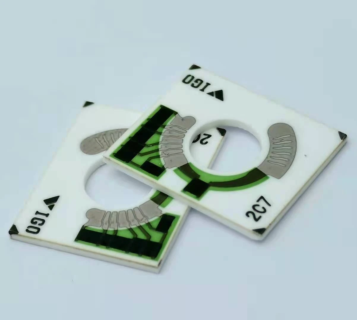
For a custom liquid-level sensor resistor card, provide the arm datum, stops, valid contact sector and the intended output-to-angle relationship. The circuit drawing and receiving software must describe the same physical coordinate. This prevents a display seam from being mistaken for a printed-track discontinuity while preserving genuine travel, contact and calibration errors that the inspection is supposed to reveal.
Provide the angular coordinate and physical travel
Include the datum and stop definition with the electrical curve.
- Resistor-card and arm drawings with active sector, stops and positive rotation.
- Reference-angle readings paired with raw resistance or voltage observations.
- Output-to-angle calibration, wrap convention and accumulated-turn requirements.
- Acceptance limits, approach direction and known acquisition gaps.
The drawing-upload form loads as you reach this section.