
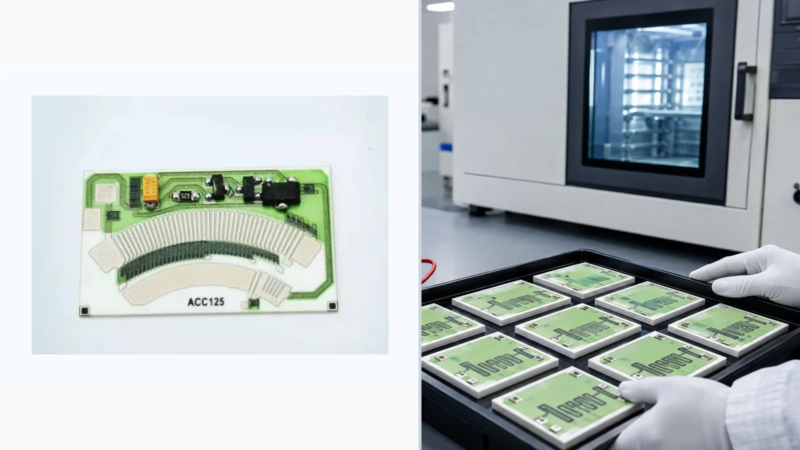
Overview
This quality method record defines Sensor Resistor Card Contact-Wear Testing through purpose, specimen condition, equipment or method, sequence, acceptance logic, and traceable output. Equipment presence alone is not proof of tolerance, range, accreditation, or released capability.
Measurement route
The order makes assumptions and ownership visible before a result is promoted to a requirement.
- 01
Translate the drawing requirement
For Sensor Resistor Card Contact-Wear Testing, control dimensions, datums, layer stack, interfaces, tolerances, and assembly constraints in the released drawing.
- 02
Condition and identify specimens
For Sensor Resistor Card Contact-Wear Testing, document the functional requirement, operating boundary, interfaces, quantities, and acceptance owner against the current drawing.
- 03
Verify method and equipment status
For Sensor Resistor Card Contact-Wear Testing, agree the inspection method, sample plan, acceptance criteria, traceability, and report format before validation.
- 04
Capture result and uncertainty
For Sensor Resistor Card Contact-Wear Testing, document the functional requirement, operating boundary, interfaces, quantities, and acceptance owner against the current drawing.
- 05
Link disposition to lot and revision
For Sensor Resistor Card Contact-Wear Testing, complete link disposition to lot and revision against the controlled drawing, named assumptions, responsible owner, required evidence, and release decision.
Engineering review matrix
Each row links a design variable to evidence that can support a drawing or release decision.
| Variable | Control question | Verification route |
|---|---|---|
| Transfer function | For Sensor Resistor Card Contact-Wear Testing, define travel or angle against resistance, ratio, voltage, curve points, endpoint behavior, and permitted error. | Measure complete forward and reverse transfer curves at controlled reference conditions. |
| Mechanical chain | Float, linkage, shaft, carrier, datum, stop, preload, and tolerance stack convert physical input into wiper position. | Correlate position with electrical output and record hysteresis and repeatability. |
| Contact interface | Wiper material, load, track finish, geometry, speed, vibration, and debris affect noise and wear. | Run contact variation, wear, interruption, and life tests with the mating contact defined. |
| Media and protection | Fuel, oil, water, additives, cleaning agents, humidity, and temperature can change track, conductor, protection, and terminals. | Expose representative assemblies under defined media, bias, temperature, time, and criteria. |
| Electronics and diagnostics | Excitation, input impedance, filtering, redundancy, plausibility, and failure detection shape usable output. | Validate channels and diagnostic states with the actual controller interface or controlled equivalent. |
Failure controls
These are review prompts, not evidence that every risk applies or that every test is available.
- A
Curve error from linkage geometry or incorrect breakpoint placement
- B
Output noise, opens, or drift from contact wear and contamination
- C
Channel mismatch or diagnostic failure in redundant tracks
- D
Media ingress, corrosion, swelling, or protection-layer damage
Inputs for a practical review
Unknown values may be labelled unknown. The review should convert uncertainty into an explicit decision or validation task.
Send Drawings- 01
Travel/angle geometry and datum scheme
- 02
Target curve table including endpoints and tolerances
- 03
Mating wiper material, load, speed, and life profile
- 04
Excitation, electronics input, diagnostics, and filtering
- 05
Media, temperature, vibration, wear, and calibration tests