
On this page
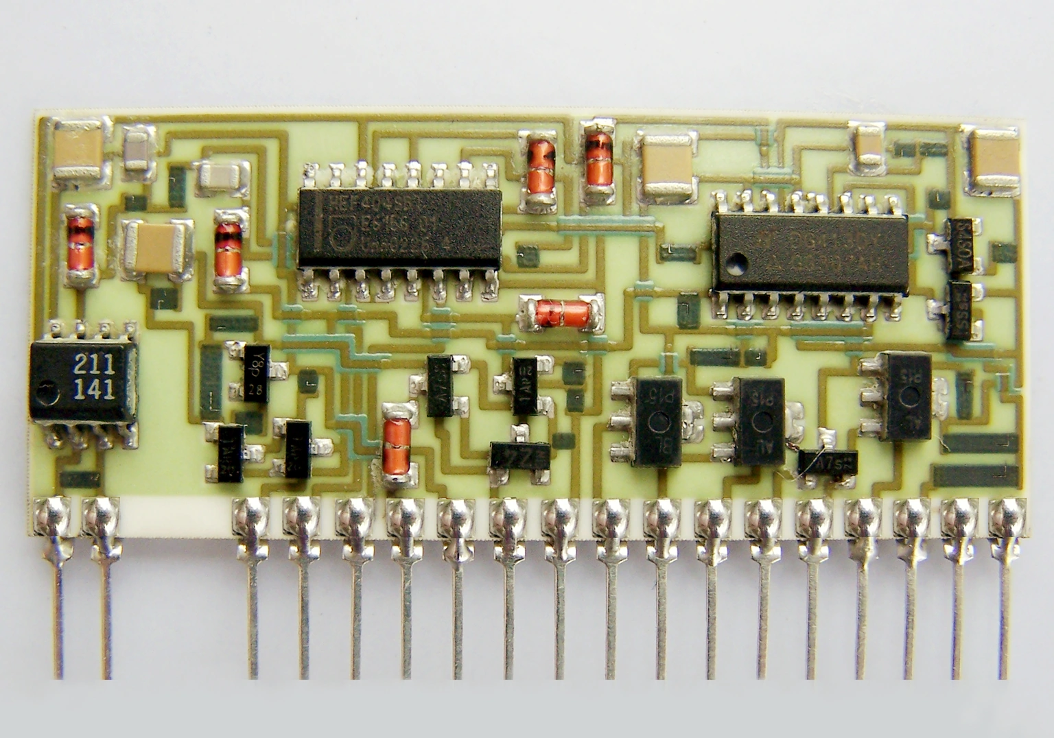
Four-wire sensing can remove much of the electrical lead-drop contribution, but it does not remove the heat carried by those same wires. Leads connected to a cooler feedthrough can pull a small ceramic circuit away from the chamber temperature. Supports and clamps add further paths. A TCR fixture therefore needs both an electrical connection definition and a thermal-boundary definition.
Measurement purpose
Determine whether lead routing or specimen support materially changes the temperature assigned to a resistance observation.
Specimens and conditions
- Representative installed specimen
- Identify ceramic dimensions, terminal construction, overglaze and the resistor region being characterized.
- Controlled attachment
- Record support contacts, clamp forces where specified, lead routing and any strain relief; avoid unsupported changes to product geometry.
Equipment and records required
- Thermal observation: Measure relevant specimen, fixture and lead-anchor temperatures with a justified nonperturbing arrangement.
- Resistance acquisition: Keep force/sense nodes, stimulus and observation timing fixed when comparing thermal arrangements.
Method sequence
- Map heat paths
Identify connections between the specimen and chamber air, fixtures, terminals and external feedthroughs.
Record: Annotated physical arrangement and temperature boundaries.
- Perform paired mounting trials
Compare justified routing or anchoring changes while preserving specimen identity and measurement definition.
Record: Actual temperatures, resistance and achieved support condition.
- Select and document the fixture
Choose a repeatable arrangement meeting thermal, electrical and mechanical requirements together.
Record: Approved setup and conditions requiring revalidation.
Decision and uncertainty
The fixture is suitable only when its thermal influence is accounted for within the required specimen-temperature uncertainty without compromising electrical or mechanical validity.
A single-node heat-flow model is only a screening approximation; distributed ceramic gradients, contacts and changing convection can require direct measurement.
The measurement owner approves the fixture boundary; product handling and electrical safety requirements remain applicable during every comparison.
Traceable outputs
| Record | Required contents |
|---|---|
| Fixture heat-path map | Lead anchors, support areas, thermal observations and electrical nodes. |
| Paired comparison report | Reference and changed arrangement, specimen history, temperature difference and resulting measurement effect. |
Method review decisions
- Treat force leads, sense leads, supports and terminals as potential thermal paths.
- Compare mounting arrangements while keeping the specimen and electrical settings matched.
- Preserve adequate electrical isolation and mechanical support when changing thermal anchoring.
Separate Kelvin sensing from thermal isolation
Force and sense separation defines where voltage is measured relative to current injection. It addresses an electrical boundary. Every physical wire can still conduct heat, including a sense wire carrying very little current. A successful four-wire check therefore does not establish the resistor's temperature.
The effect can be important on a small ceramic coupon with relatively large terminals or short leads to a cooler fixture. On another construction it may be negligible. Evaluate the actual ratio of thermal paths rather than assigning a universal error to all four-wire arrangements.
Estimate which lead paths deserve measurement
For a uniform lead with approximately constant thermal conductivity, a first estimate of conductance is kA/L. Increasing cross-sectional area or shortening the unanchored length strengthens that path. The temperature at the far end of the segment determines whether it removes heat from or supplies heat to the specimen.
This screening calculation omits connector contacts, insulation, distributed convection and temperature-dependent properties. Use it to identify influential paths, not to certify a TCR fixture from wire gauge alone. Electrical current capacity, mechanical reliability and insulation requirements may prevent simply selecting the thinnest possible lead.
Glead ≈ kA/L; Qlead ≈ Glead(Tspecimen − Tanchor)
- Glead is thermal conductance in W/K, k is conductivity in W/(m·K), A is area in m² and L is path length in m.
- Qlead is the estimated heat flow toward an anchor colder than the specimen.
One-dimensional steady conduction through a uniform segment with negligible lateral losses; real fixtures require additional paths and measured validation.
Calculate a simple competing-path example
Assume a hypothetical specimen has 0.020 W/K conductance to a 75 °C environment and 0.002 W/K through leads to a 25 °C anchor. Neglecting electrical power and other paths, the single-node balance gives a specimen temperature of approximately 70.45 °C. The chamber value alone would overstate that temperature by about 4.55 K.
If the lead anchor is brought to the same 75 °C boundary without changing other conditions, this simplified model predicts no lead-induced offset. Real thermal anchoring may introduce gradients or change lead mechanics, so the example identifies a comparison to verify rather than prescribing a particular anchor construction or claiming an actual product temperature.
Include supports, clamps and ceramic contact regions
A metal support touching the substrate can dominate the thermal boundary even when the leads are carefully routed. Record contact area, position and the temperature of the support itself. Two fixtures with identical chamber setpoints may expose the resistor to different substrate gradients.
Do not let terminals or solder joints become unintended support points. Changes in clamp position can affect both heat flow and mechanical strain, complicating the comparison. Preserve a mechanically appropriate support arrangement and evaluate alternative thermal contacts only within the product's approved handling requirements.
Change one heat-path condition in a paired trial
Use the same identified specimen where appropriate and compare a reference routing with a justified alternative. Retain the electrical nodes, current, aperture and thermal sequence. Record actual temperatures near the resistor and at the relevant anchors so a resistance change can be interpreted physically.
A return to the original arrangement is useful for detecting history or mounting effects. If the final reference arrangement no longer reproduces the starting state, do not attribute the entire difference to the lead change. Investigate exposure history, contact movement and specimen condition before concluding that one fixture is thermally superior.
Select the investigation from the observed response
A fixture comparison should identify which thermal boundary changed and whether the assigned specimen temperature remains valid. Keep electrical and mechanical changes visible alongside thermal observations.
| Observed response | Heat path to examine | Controlled comparison |
|---|---|---|
| Specimen offset follows external feedthrough temperature | Unanchored lead conduction | Alter justified thermal anchor while retaining electrical nodes |
| Resistor regions differ across one ceramic | Support or terminal-induced gradient | Measure locations and compare approved support geometry |
| Resistance changes after remounting at matched temperature | Contact or strain contribution | Repeat seating without changing thermal program |
| Offset changes strongly with chamber load | Convection and fixture coupling | Repeat representative load configurations |
| Lower stimulus reduces the apparent offset | Measurement self-heating | Compare power with matched timing and support |
Verify what the temperature sensor represents
A probe attached to the fixture may observe the fixture accurately while failing to represent the resistor region. A probe attached to the ceramic can itself add a heat path. Choose placement and attachment from the required uncertainty and compare plausible alternatives where the perturbation could be significant.
A companion substrate can be useful only if its dimensions, terminal loading and location represent the test specimen sufficiently. Do not assume that a bare ceramic witness tracks a fully terminated circuit. Preserve the relationship between the thermal proxy and the actual measured resistor in the controlled method.
Transfer a fixture with both boundary definitions
The fixture record should include photographs or drawings of lead routes and support contacts, electrical node labels, anchor temperatures and the evidence supporting specimen-temperature assignment. Specify which details are critical to repeatability so another operator cannot reproduce the wiring while accidentally changing the heat path.
Reassess after changing terminal size, cable route, support material, chamber load or specimen format. A fixture validated for one ceramic construction is not automatically valid for every resistor geometry. For customer test planning, provide the proposed mounted configuration so electrical accuracy and thermal representativeness can be reviewed together.
Review the electrical and thermal test fixture
Send the specimen construction and complete lead/support arrangement used during the temperature test.
- Ceramic and terminal geometry, resistor location and support contacts.
- Force/sense nodes, lead routes, anchors and external feedthrough conditions.
- Measured specimen and fixture temperatures with stimulus and timing.
- Required temperature uncertainty and permitted mechanical handling conditions.
The drawing-upload form loads as you reach this section.