
On this page
A chamber can reach its displayed setpoint while the ceramic circuit, fixture and electrical leads are still approaching a different thermal state. Calculating TCR with the controller number then assigns a resistance reading to a temperature the resistor may never have reached. Record the specimen-associated temperature and define a defensible stabilization criterion before interpreting a small coefficient as material performance.
Measurement purpose
Establish a traceable specimen-temperature basis for each resistance observation in the specified TCR interval.
Specimens and conditions
- Actual circuit construction
- Identify ceramic size, resistor location, overglaze, attached terminals and fixture support because they influence thermal response.
- Defined excitation
- Retain measurement current or voltage and duty; compare a lower-power condition where self-heating could be significant.
Equipment and records required
- Temperature measurement chain: Use an appropriate calibrated probe and readout with documented attachment, position, uncertainty and response behavior.
- Synchronized resistance record: Associate the electrical observation window with the temperature record rather than a manually copied controller setpoint.
Method sequence
- Characterize placement
Compare the control indication with specimen-associated temperature under representative loading and lead routing.
Record: Probe map, load and time histories.
- Establish a usable plateau
Apply justified limits to local movement, spatial differences and reading-window timing.
Record: Stabilization assessment and accepted observation interval.
- Calculate with actual temperatures
Use the temperatures paired with resistance observations and propagate relevant temperature uncertainty.
Record: Actual interval, coefficient and thermal contribution.
Decision and uncertainty
Use an observation only when its assigned temperature represents the specified specimen state within the required uncertainty.
Calibration uncertainty does not include every attachment gradient, probe lag or resistor self-heating effect; each relevant contribution requires evaluation.
The thermal-method owner approves temperature assignment and plateau criteria; the product requirement defines the coefficient interval and allowable uncertainty.
Traceable outputs
| Record | Required contents |
|---|---|
| Specimen-temperature record | Probe location, calibrated chain, time history, excitation and selected resistance windows. |
| Thermal validity assessment | Controller-to-specimen differences, plateau criterion, gradients and remaining uncertainty. |
Method review decisions
- Distinguish programmed setpoint, chamber control sensor and specimen-associated temperature.
- Set thermal-state criteria from the required resistance and coefficient uncertainty, not an arbitrary universal dwell.
- Verify that the temperature probe and electrical excitation do not materially change the state being measured.
Keep three temperature values separate
The programmed setpoint is a command. The control sensor reports a location used by the chamber controller. A specimen probe observes another location, with its own coupling and response time. Agreement among these values can be useful, but none should be silently substituted for another.
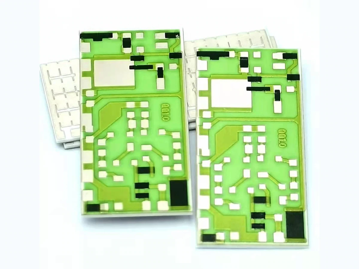
For a ceramic thick-film circuit, the resistor region may differ from the surrounding air because of support contact, terminal conduction or measurement power. Describe what the probe actually observes: adjacent air, substrate backside, a nearby surface or a representative companion specimen. Each is a different thermal proxy requiring justification.
See how an interval error changes the reported coefficient
Assume an illustrative resistor changes from 1,000.00 to 1,002.00 ohms between two actual specimen temperatures separated by 50 kelvin. The endpoint coefficient normalized by the first resistance is 40 ppm/K. If a 52-kelvin controller interval is substituted, the calculation gives approximately 38.46 ppm/K.
The resistance readings did not improve; the denominator changed. This example isolates interval error and assumes the endpoint resistances themselves are correct. In a real test, a wrong temperature assignment can also mean the observed resistances belong to different physical points on a curved resistance-temperature characteristic.
Choose probe placement from the relevant heat path
Place the temperature observation near the resistor region while preserving electrical isolation and the product surface. An attachment on a heavy metal fixture can lag or lead the ceramic and may be inappropriate even when it gives a stable reading. Document the probe's physical position with enough detail to repeat it.
Evaluate whether the attachment changes local convection, conduction or radiation. Adhesive, tape and a relatively large probe can perturb a small substrate. A companion specimen can reduce interference with the measured circuit, but its construction, placement and loading must represent the relevant thermal response rather than merely sharing a shelf.
Define stabilization as an observation criterion
A defensible plateau criterion considers temperature movement over the electrical observation window, differences among relevant locations and repeatability after a further wait. It should be linked to the required coefficient uncertainty. A fixed delay may be convenient once validated, but it is not evidence by itself that every load has equilibrated.
For illustration, if an approximately 100-ppm/K response is used only to assess sensitivity, a 0.2-kelvin temperature movement corresponds to about 20 ppm of resistance movement. Whether that matters depends on the actual resistance and acceptance requirement. Use the relevant bounded sensitivity instead of adopting this hypothetical coefficient as a material value.
Respond to the thermal pattern actually observed
A stable controller display can coexist with each of the following conditions. Preserve the time history so a failed thermal-state check leads to a targeted investigation rather than an unrecorded extension of the dwell.
| Observation | Interpretation to examine | Required evidence before use |
|---|---|---|
| Controller stable, ceramic temperature moving | Specimen or support remains in transient response | Local plateau within the defined reading window |
| Both stable but at different temperatures | Persistent spatial or conductive offset | Justified actual specimen temperature assignment |
| Probe stable, resistance changes with current | Self-heating may occur at the resistive film | Excitation comparison with controlled timing |
| Different specimen positions disagree | Load-dependent spatial distribution | Position-associated temperature records |
| Probe movement depends on attachment | Measurement may perturb the specimen | Repeatable placement or validated alternative proxy |
Check the electrical stimulus as a heat source
Resistance acquisition deposits electrical power in the film. Low average power may still produce a transient during the measurement window, especially with a concentrated geometry or weak thermal path. Retain the stimulus duration and not only the nominal current setting.
Compare justified excitation levels without changing contacts or acquisition timing unnecessarily. A systematic resistance change with power suggests a thermal or voltage-dependent contribution that requires separation. Do not automatically extrapolate to zero power with a straight line unless the response and uncertainty support that model over the measured range.
Align the temperature record with resistance acquisition
A temperature read before a long scanner sequence may not describe the last resistor measured. Record timestamps and observation windows for both channels. If the environment changes during the sequence, use a justified interpolation or shorten and redesign the sequence rather than attaching one temperature to every row.
The probe's response time also matters. Fast logging of a slow sensor does not remove its lag. When a stable plateau is not established, reconstructing specimen temperature from a lag model requires an independently supported dynamic model; it should not become an automatic software correction used to justify early readings.
Report the achieved thermal state and its limitations
For each coefficient, retain actual endpoint temperatures, resistance readings, probe arrangement and the criterion used to select the observations. Include heating or cooling direction and any return-to-reference measurements. A concise temperature assignment record is more useful than a chamber screenshot alone.
Changing substrate dimensions, terminal configuration, load density or mounting can invalidate a previously established delay. Review the thermal-state basis after those changes. The result then remains tied to a specified circuit and test arrangement, allowing customers to evaluate whether the evidence applies to their intended construction and temperature interval.
Specify the TCR thermal measurement boundary
Provide the circuit construction and temperature requirement together with how temperature will be observed at the specimen.
- Ceramic dimensions, resistor location, attached parts and support arrangement.
- Temperature interval, required coefficient uncertainty and reporting convention.
- Probe placement, calibration information and time-aligned resistance data.
- Excitation settings, plateau criterion and chamber load configuration.
The drawing-upload form loads as you reach this section.