
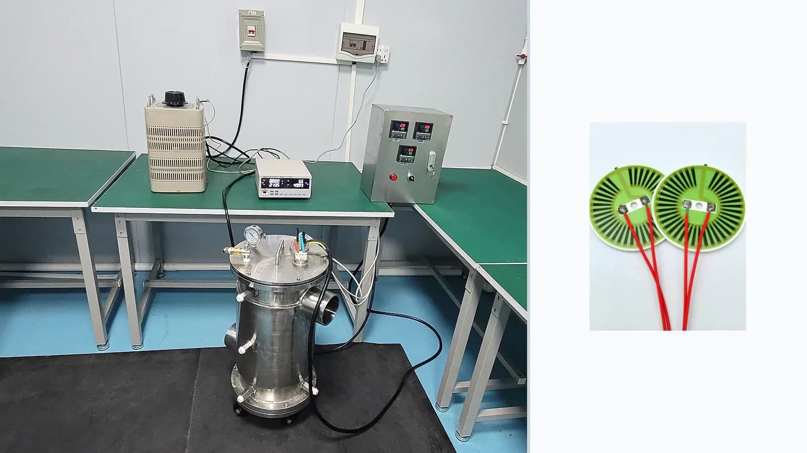
Overview
This quality method record defines Thick Film Heater Thermal Mapping through purpose, specimen condition, equipment or method, sequence, acceptance logic, and traceable output. Equipment presence alone is not proof of tolerance, range, accreditation, or released capability.
Measurement route
The order makes assumptions and ownership visible before a result is promoted to a requirement.
- 01
Translate the drawing requirement
For Thick Film Heater Thermal Mapping, control dimensions, datums, layer stack, interfaces, tolerances, and assembly constraints in the released drawing.
- 02
Condition and identify specimens
For Thick Film Heater Thermal Mapping, document the functional requirement, operating boundary, interfaces, quantities, and acceptance owner against the current drawing.
- 03
Verify method and equipment status
For Thick Film Heater Thermal Mapping, agree the inspection method, sample plan, acceptance criteria, traceability, and report format before validation.
- 04
Capture result and uncertainty
For Thick Film Heater Thermal Mapping, document the functional requirement, operating boundary, interfaces, quantities, and acceptance owner against the current drawing.
- 05
Link disposition to lot and revision
For Thick Film Heater Thermal Mapping, complete link disposition to lot and revision against the controlled drawing, named assumptions, responsible owner, required evidence, and release decision.
Engineering review matrix
Each row links a design variable to evidence that can support a drawing or release decision.
| Variable | Control question | Verification route |
|---|---|---|
| Electrical target | For Thick Film Heater Thermal Mapping, define voltage, resistance, current, power, duty cycle, and tolerance at the assembly operating point. | Measure cold and operating resistance, current, power, and protective response under the agreed supply condition. |
| Heat path | Substrate, mounting, fluid or air flow, contact resistance, insulation, and ambient determine temperature—not nominal watts alone. | Map temperature at steady state and during transients at relevant boundary conditions. |
| Printed geometry | Trace width, thickness, turns, spacing, neck-downs, and terminal transitions control local current density and heat flux. | Inspect processed geometry and correlate critical regions with the thermal map. |
| Insulation and protection | Working voltage, dielectric stack, creepage, clearance, moisture, scale, and dry-run exposure must be reviewed together. | Use a construction-specific insulation, dielectric, leakage, and environmental plan. |
| Control interface | Sensors, cut-outs, bonding, terminals, control algorithm, and fault state belong to the heater system boundary. | Validate warm-up, overshoot, cycling, sensor response, and defined fault cases in the final assembly. |
Failure controls
These are review prompts, not evidence that every risk applies or that every test is available.
- A
Local hot spot at a turn, neck-down, terminal, void, or poor thermal interface
- B
Resistance drift or protection damage after thermal cycling
- C
Dielectric breakdown, leakage, or corrosion under moisture, scale, or contamination
- D
Runaway temperature when flow, contact, sensing, or control is lost
Inputs for a practical review
Unknown values may be labelled unknown. The review should convert uncertainty into an explicit decision or validation task.
Send Drawings- 01
Supply voltage and tolerance; target power or resistance
- 02
Thermal load, mounting stack, medium, flow, ambient, and duty cycle
- 03
Allowed temperature field, warm-up time, and fault limits
- 04
Outline, keep-outs, terminal and sensor interfaces
- 05
Electrical, thermal, cycling, and safety tests