
On this page
An AC withstand result cannot be relabeled as a DC result by changing the voltage number. Matching the peaks of two ideal waveforms matches one feature of the applied stress, not the complete test. Current, polarity history, field distribution and stored charge can differ. Before accepting an existing record for a ceramic circuit or heater assembly, compare the actual method with the requirement it is intended to satisfy.
Key design decisions
- Retain waveform, frequency, polarity, timing and current definition with every withstand result.
- Treat peak matching as arithmetic, not permission to substitute a test method.
- Check the source's capacitive load requirement before interpreting a current trip.
- Have the responsible system safety engineer approve any method substitution and its evidence.
1. Establish exactly what is being substituted
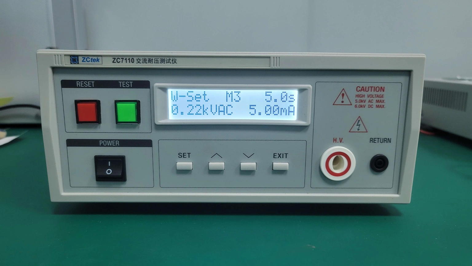
Identify the original test and the requested replacement in separate columns. Include the circuit revision, connected nodes, conditioning, waveform, voltage convention, duration and decision rule. An AC instrument photograph and a pass label do not establish that the required DC sequence was performed, even when both instruments can display the same numerical voltage.
Distinguish a diagnostic comparison from a conformity decision. Engineering can study how a known assembly responds to two waveforms, but that study does not itself authorize replacing an approved acceptance method. The governing equipment requirement, component construction and responsible review determine which evidence is acceptable. Do not infer permission from the available tester or from a convenient conversion factor.
2. Match the voltage convention before comparing numbers
For an ideal sinusoid with no DC component, peak voltage is the RMS value multiplied by the square root of two. Thus an assumed 100 V RMS sinusoid reaches approximately +141.42 V and −141.42 V. A constant +141.42 V DC waveform matches its positive maximum but never reverses polarity.
This deliberately low numerical example illustrates the convention only; it is not a proposed acceptance voltage. A distorted AC waveform or one with a DC offset does not necessarily follow that simple RMS-to-peak relation. Record the actual waveform or an appropriate verified characterization when the difference matters. Peak-to-peak voltage, peak magnitude and RMS are three different quantities and must not share an unlabeled voltage field.
v(t) = √2 Vrms sin(2πft); Vpeak = √2 Vrms
- Vrms is the RMS voltage of the stated ideal sinusoid in volts.
- Vpeak is its maximum magnitude in volts.
- f is frequency in hertz and t is time in seconds.
Pure sinusoidal alternating voltage with no DC offset. This relationship does not establish AC/DC test equivalence or any product test-voltage requirement.
3. Calculate the alternating current that exists without a conductive defect
A capacitance carries current continuously under alternating excitation, even in the ideal lossless limit. For sinusoidal voltage its RMS current is 2πfCVrms. That load remains during the AC hold; it is not simply the initial charge associated with a DC voltage rise.
For an assumed 10 nF capacitance at 100 V RMS, the capacitive current is about 0.3142 mA at 50 Hz and 0.3770 mA at 60 Hz. Increasing frequency by 20% increases this ideal current by 20% without changing insulation resistance. The source must maintain the required waveform under the actual combined specimen, cable and fixture load. Failure to reach the requested voltage is a different event from a correctly applied stress followed by specimen breakdown.
4. Do not transfer the current threshold without its measurand
The total AC current can include an in-phase contribution and a quadrature capacitive contribution. In a simple linear parallel resistance-capacitance model these components combine vectorially. Their RMS magnitudes do not add arithmetically, and the ratio Vrms divided by total current is an impedance magnitude rather than an insulation resistance.
Using the 50 Hz example, add an assumed in-phase current of 0.1000 mA. Total current becomes approximately 0.3297 mA, from the square root of 0.3142² plus 0.1000². Dividing 100 V by that total gives approximately 303 kΩ, although the assumed resistive branch is 1 MΩ. The in-phase current may itself include dielectric loss, so even a phase-separated reading is not automatically the steady DC conduction result.
5. Keep polarity history and stack response in the review
A sustained DC exposure and a reversing field need not distribute voltage identically through a multilayer insulation system. Capacitive division, finite conductivity and interfacial charge describe different limiting behavior. An identical external peak does not establish an identical local field throughout a fired dielectric, protective coating and neighboring interface.
Retain the actual material sequence and the time or frequency conditions used to interpret it. Do not turn this distinction into a blanket claim that AC is always harder or DC is always easier. The relevant weakness may be a bulk layer, a contaminated surface, an edge or an attached component, and the method must address that specific construction. Connected suppression or sensing components also require explicit inclusion or isolation decisions.
6. Include the final electrical state, not only the hold interval
The DC method can leave the specimen and fixture charged after its stress interval ends. For an ideal capacitance, stored energy is one half of capacitance times voltage squared. The assumed 10 nF at 141.42 V contains approximately 0.000100 J; multiplying capacitance by ten multiplies that energy by ten, while doubling voltage multiplies it by four.
Those arithmetic relationships do not define a safe handling threshold or a discharge time. Real fixtures can contain additional capacitance and dielectric recovery behavior. Use qualified personnel, rated test arrangements, protective enclosure or interlocks and the actual instrument's approved discharge and verification procedure. Preserve the same control after an interrupted or failed test. A completed software step or a passing judgment is not permission to touch an unverified electrical boundary.
7. Identify which missing field prevents reuse of the record
A reusable report needs the conditions that distinguish the two methods. Resolve missing information with the original record or an approved additional evaluation rather than filling it with an assumed equivalence.
| Difference or omission | Required resolution | Invalid shortcut |
|---|---|---|
| Voltage listed without RMS or peak convention | Recover the waveform and measurement definition | Apply a fixed factor to an unlabeled value |
| Different AC frequencies | Review capacitive load and specified stress frequency | Assume the same total current at equal voltage |
| Total AC current compared with DC leakage | Identify current components and the actual acceptance measurand | Convert every V/I result into insulation resistance |
| Multilayer construction changed | Review local field and time-dependent response | Count only total insulation thickness |
| Other circuit components connected differently | Reconstruct the tested node boundary | Treat two external test clips as proof of identical paths |
| Discharge or interruption state absent | Confirm the approved handling sequence and controls | Infer electrical safety from a pass flag |
8. Deliver a method-compatibility decision with explicit scope
The engineering outcome should state whether the existing record directly satisfies the named requirement, whether an explicitly permitted substitution is supported, or whether a different evaluation is needed. Keep the reason tied to waveform, construction and method rather than to a preference for one kind of instrument.
Provide the supplier and system team with the exact tested boundary and any unresolved difference. If additional comparisons are approved, retain actual voltage and current behavior instead of collecting only a second pass label. This makes later changes to fixture capacitance, connected electronics or layer construction reviewable without recreating the ambiguity that prompted the comparison.
Send both withstand-method definitions
A waveform-compatibility review needs the original result and the requirement it must answer.
- Original and requested methods with waveform, frequency, polarity and voltage convention
- Named circuit nodes, material stack and components included or isolated during each test
- Actual voltage/current record, source compliance state and current-decision definition
- Conditioning, ramp, hold, end-state and prior stress history
- Governing equipment requirement and responsible approval for any substitution
- Fixture capacitance and the qualified discharge and handling procedure
The drawing-upload form loads as you reach this section.