
On this page
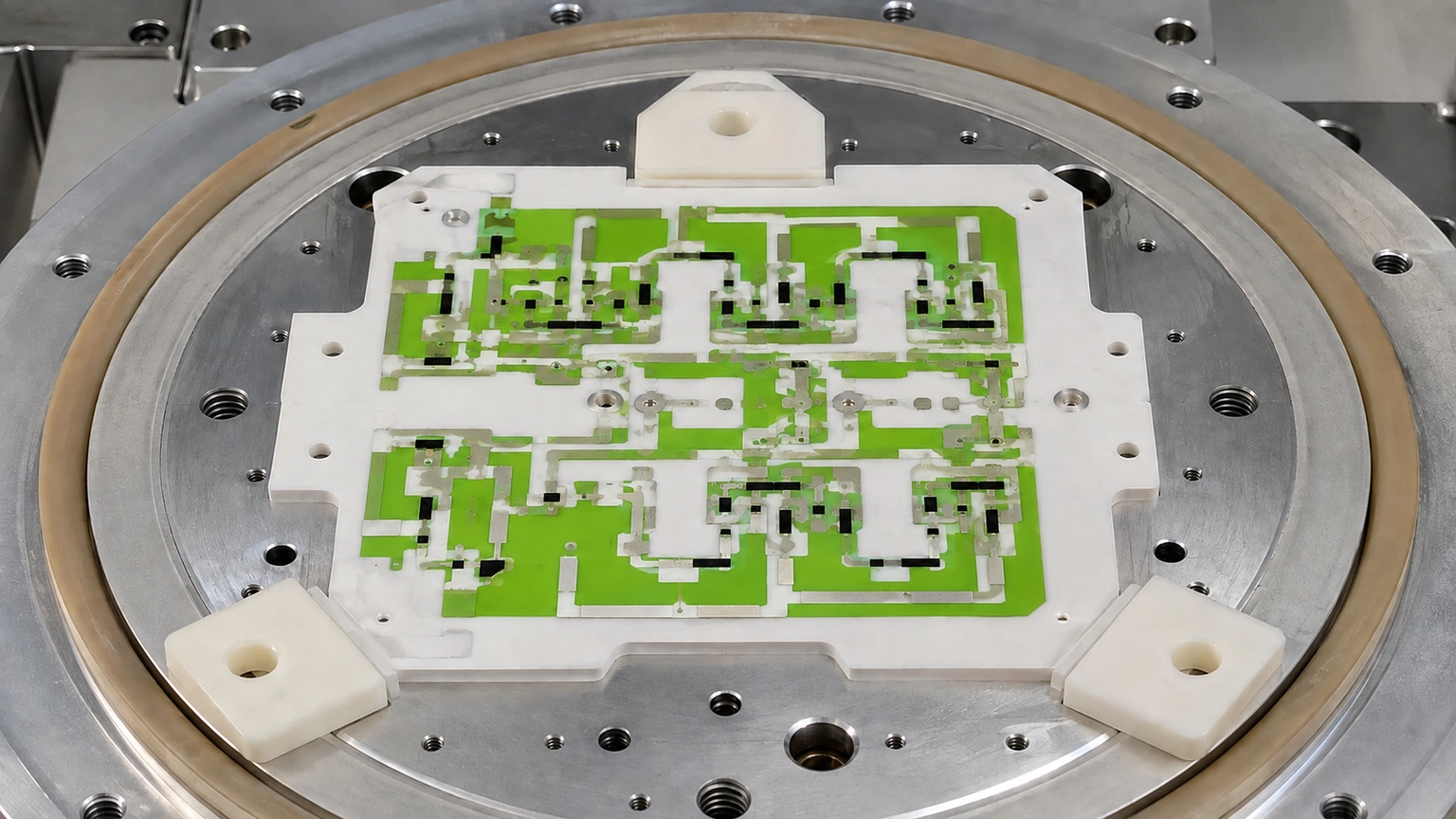
Flipping a ceramic part turns first-side conductors, resistors and glaze edges into fixture interfaces. Average clamp pressure can appear small while a narrow support ridge carries most of the force. The design task is therefore geometric: map relief and support footprints against actual first-side height, registration and part flatness.
Key design decisions
- Mirror first-side geometry into fixture coordinates
- Provide support on stable ceramic regions
- Inspect local witness marks after clamping
- Validate both faces after the complete sequence
1. Mirror first-side features into fixture coordinates
Transform first-side artwork into the fixture coordinate system using an explicit flip axis and face convention. Mark conductors, resistors, glaze edges, components and raised terminals that will face the support during second-side printing. Do not mirror by eye. Include part outline and datum tolerances so the relief remains aligned at worst case. A symmetric outline does not prove face identity; preserve keyed carrier orientation and traveler records from first-side firing through fixture loading.
2. Define prohibited contact over functional films
Classify contact zones by function. Bare ceramic regions may be candidates for support, while active resistors, narrow conductors, wire-bond pads and brittle glaze edges normally require drawing-specific relief. A broad conductor may tolerate handling yet remain unsuitable as a repeated force datum. Record the reason for each keep-out and the minimum observed relief, rather than colouring all printed areas identically. Unknown first-side height or function is a hold, not permission to assume a flush surface.
3. Support stable ceramic regions without creating rocking
Use three or more well-placed support regions where appropriate to establish a stable plane without overconstraint. Check whether bowed ceramic or local deposits make the part rock between high points. A compliant support can distribute load but may change print height or registration; a hard support can concentrate stress. Inspect seating with representative fired parts, not an ideal blank. If fixtures contact panel rails, confirm those rails remain connected and planar throughout the intended process state.
4. Stack fixture, registration and topography tolerances
Build a signed stack from part-datum variation, fixture machining, loading clearance, first-side feature height and second-side registration. Worst-case and statistical treatments answer different questions and require justified independence. A relief drawn exactly to the nominal feature boundary has no allowance for lateral error. Include thermal or wear changes if they are material to use. Keep the stack in length units and show which contributor controls the remaining gap or overlap.
5. Treat average clamp pressure only as a screen
Average pressure p=F/A is only an initial screen. Six newtons distributed across 30 mm2 gives 0.20 MPa, but a narrow ridge or particle can carry much more locally. Record clamp force, support contact area and load path. Pressure cannot be converted into film safety without material and geometry evidence. Use pressure-sensitive media or suitable witness methods cautiously because they may alter seating. Avoid increasing clamp force merely to stop rocking before correcting the support geometry.
Fixture contamination can become a new high point. Inspect support faces before loading and define cleaning that does not leave hard particles. A single ceramic chip on an otherwise compliant pad can concentrate force. Record fixture condition with each trial and quarantine parts loaded after a confirmed debris event until their contact regions are examined.
pavg=F/A
- Variables refer only to the quantities named in the worked example.
- Units must remain explicit and inputs must share the stated reference state.
A 6 N clamp force distributed over 30 mm2 gives 0.20 MPa average pressure. A sharp ridge can create a much higher local stress. The numbers are hypothetical and do not define acceptance.
6. Inspect every support footprint after clamping
After representative clamping, inspect every planned support footprint and adjacent film for polish marks, debris, cracks, glaze impressions or changed topography. Use stable lighting and a pre-clamp image. A clean central area does not clear an unobserved edge contact. Measure resistance on mapped first-side features when force sensitivity is plausible, with an unclamped or relief-correct control. Preserve any damaged part before repeated clamping obscures the initial contact mark.
Relief depth must accommodate topography and seating without allowing excessive lateral motion. Increasing every pocket depth can reduce damage yet worsen registration or vacuum response. Evaluate relief, locating datums and clamp path together. Use section or profilometry data only when its reference plane corresponds to the fixture design.
| Observed pattern | What remains unresolved | Next controlled comparison |
|---|---|---|
| Marks coincide with support edges | Local contact concentration is likely | Increase relief or redistribute support |
| Registration shifts only after flipping | Rocking or datum transfer may be involved | Measure seated condition and support heights |
| First-side resistance changes after support | Film loading is plausible | Move contact to ceramic and repeat a paired clamp cycle |
7. Verify registration and resistance after the flip
Run the full flip, seat, print and unload sequence while monitoring second-side registration and first-side electrical state. A shift only after flipping may come from datum inversion, rocking or fixture contact; separate these with a stationary reference and seating check. Paste on the second face must not be blamed for a first-side resistance step recorded before firing. Repeat independent loading cycles and fixture positions rather than counting multiple fiducials on one seated part as independent events.
If a support must contact a printed region, require explicit evidence for that material, geometry, force and cycle count. A one-time visual check is not repeated-use validation. Measure relevant electrical or surface response before and after controlled cycles and preserve an all-ceramic support alternative for comparison where the layout permits.
8. Release a face-aware fixture revision
Release the fixture with face-labelled drawings, transformation definition, first-side keep-outs, support coordinates, relief depth, force setting, tolerance stack, inspection record and revision control. State which fired topography and panel state were tested. The record does not claim ceramic strength, allowable film pressure, registration capability or fixture life. A first-side material, thickness, layout, panel rail or clamp change reopens the support review before second-side production use.
The RFQ package should distinguish desired second-face registration from allowable first-face contact. Supply both face drawings in one coordinate convention, expected fired heights, panel state and fixture access. Without those inputs, engineering can review the concept but cannot approve relief dimensions or claim that an unseen first-side feature is protected.
Cycle count should represent the proposed use of the fixture. A single clamp can reveal gross interference, while repeated loading may polish a glaze edge, accumulate debris or loosen a locating feature. Use independent parts and mapped repeated-cycle witnesses without treating repeated clamps on one part as independent samples. Inspect the fixture as well as the ceramic. If registration changes gradually with cycle count, distinguish fixture wear from screen drift by measuring a stationary reference and a clean, unloaded seating check.
Before release, perform a peer check of the mirrored coordinate convention using one named feature on each face. Confirm that the support drawing, inspection image and traveler use the same face names. This simple check prevents a correct relief pattern from being manufactured or loaded in the opposite orientation.
Send the double-sided support contact decision inputs
Send both-face artwork, fired first-side height data, support and relief drawings, clamp information and before-and-after inspection evidence for review.
- Drawing revision and functional requirement for double-sided support contact
- Mirror first-side geometry into fixture coordinates
- Provide support on stable ceramic regions
- Calculate average pressure only as a screening value
- Raw measurements, units, uncertainty and excluded observations
- Validate both faces after the complete sequence
The drawing-upload form loads as you reach this section.