
On this page
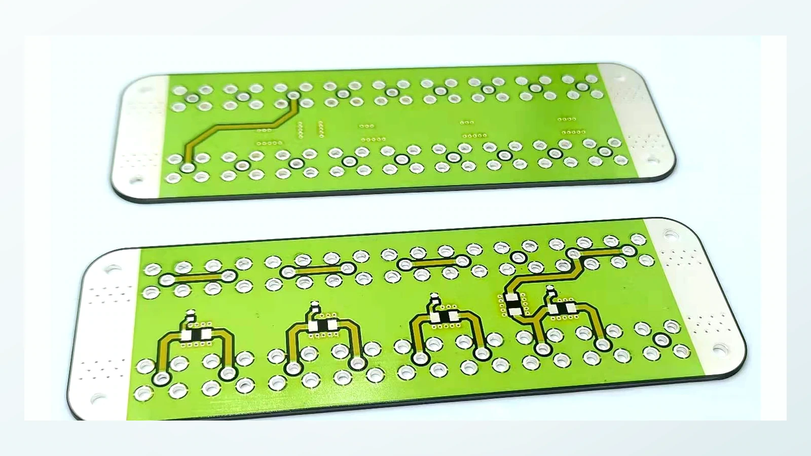
A double-sided ceramic circuit has one mechanical identity even when its two printed faces are prepared and inspected separately. Connector position, through-hole location and the assembled outline must agree in the same coordinate system. A drawing that gives accurate dimensions on each face can still produce a poor assembly if the back view is mirrored inconsistently or each operation chooses a different locating edge. The practical design task is to connect the functional mating features to stable datums, then preserve that relationship through artwork, fixtures, firing, inspection and assembly.
Key design decisions
- Choose the locating features from the installed assembly, not from whichever ceramic edge is easiest to see in a photograph.
- State how the back face is viewed and transformed, including the rotation axis, origin and positive directions.
- Allocate the connector alignment budget across ceramic geometry, both printed faces, fixture seating and mating-part variation.
Start with the features that locate the installed circuit
Identify what actually restrains the ceramic in the housing. A pair of holes, an edge against a stop and a supported face establish different constraints. The contact pads may need to align with spring contacts while the ceramic outline is allowed to float. In that assembly, centering all artwork on the outside rectangle does not necessarily protect the electrical interface.
Select a primary support surface, a directional locating feature and a final orientation feature appropriate to the assembly. Distinguish locating holes from clearance holes. A generous clearance hole cannot simultaneously provide precise in-plane location unless a separate controlled contact is defined. Record which features must remain free to accommodate thermal movement and which carry the connector alignment requirement.
Make the back-face viewing convention explicit
A back-face drawing can mean looking directly at the back surface or viewing the back pattern through the front. These representations are mirror images. Supply an annotated coordinate definition rather than relying on a label such as bottom layer. Include an asymmetric orientation marker and a known feature whose position can be checked without interpreting a dense circuit pattern.
For a flip about a vertical axis, the horizontal coordinate reverses relative to the chosen origin while the vertical coordinate is preserved. A subsequent rotation changes the transformation again. Check at least three non-collinear features through the entire transformation. Agreement at a single central hole can conceal a mirror error because that point may be unchanged by the transformation.
Allocate a mating-feature alignment budget
Treat the permitted misalignment as an assembly allowance rather than a printing-only tolerance. Include the ceramic datum-to-hole relationship, pattern registration to those datums, fixture seating repeatability and the mating connector location. If both faces independently connect to a third component, calculate both functional relationships rather than checking front-to-back artwork alone.
A conservative stack adds bounded positional contributions in the direction that closes the contact margin. A statistical stack requires distributions and independence assumptions; repeated biases do not disappear through root-sum-square arithmetic. Preserve separate horizontal and vertical budgets when contact geometry is directional. A long rectangular pad may tolerate movement along its length but lose usable contact overlap rapidly across its width.
Mremaining = Mavailable − (Eceramic + Eprint + Efixture + Emating)
- Mavailable: permissible functional misalignment in the evaluated direction
- E terms: bounded positional contributions expressed in the same units
- Mremaining: unallocated alignment margin
A conservative one-direction stack with all errors acting to reduce the available margin; it is not a statistical yield prediction.
Match each inspection to its functional relationship
The inspection plan should name the relationship being measured, not merely list dimensions. A printed pad measured relative to an arbitrary image corner cannot verify connector fit when the assembly locates from a hole. Preserve the same datum logic even if different instruments are used for the ceramic and printed patterns.
| Relationship | What establishes it | What a failed check suggests |
|---|---|---|
| Front pads to locating holes | Front artwork and physical hole datums | Registration or datum interpretation error |
| Back pads to locating holes | Explicit back-face transformation | Mirroring, rotation or back-fixture error |
| Front vias to back capture pads | Common coordinate definition and actual holes | Combined printing and drilling displacement |
| Connector contact to usable pad region | Installed seating plus mating component | Assembly stack or insufficient contact margin |
Keep fixture seating from becoming an uncontrolled datum
A fixture can reproduce a drawing origin poorly if debris, burrs or local ceramic warpage change how the part seats. Define the intended contacts and leave non-locating regions clear. Supporting a bowed part at many uncontrolled points may produce a different in-plane location each time the clamp is applied.
Evaluate repeated removal and replacement of the same substrate before attributing scatter to printing. Check whether clamping changes a measured hole-to-pad relationship or only the image coordinate origin. Record contact condition and seating method when comparing front and back results. A fixture that uses a different edge on each face needs an explicit transfer measurement between those edges.
Separate substrate geometry from printed-pattern movement
Measure the ceramic locating features before and after the relevant thermal sequence if dimensional stability is important to fit. Also inspect fired patterns rather than assuming the wet printed outline represents the final electrical boundary. Material suppliers distinguish processing stages and substrate families; the drawing must identify the state in which its dimensional requirements apply.
- Use the same part identity for before-and-after comparisons so population differences do not mimic process movement.
- Compare a pattern's position and its size separately; a translated pattern and a distorted pattern require different corrections.
- Record whether a final overglaze opening, rather than the underlying metal pad, limits the usable contact area.
Diagnose disagreement without moving both artworks
When mating fails, first check orientation and part identity. Next repeat the mechanical datum measurement with the part removed and reseated. Then compare front and back patterns separately to the physical datums. Only after those checks should artwork offsets be considered. Moving both patterns to compensate for a fixture fault can create apparently good samples while leaving the underlying coordinate problem intact.
Use a simple asymmetric verification coupon or a clearly identified production feature set for transformation checks. The verification should make an incorrect mirror or rotation immediately apparent. Retain the failed measurement and the corrected coordinate calculation together so the next operation does not restore the earlier interpretation.
Deliver a coordinate package that can be checked independently
Provide the mechanical drawing, named artwork layers, origin convention and a small coordinate table of functional points. Include the expected front-to-back transformation in plain language and state which dimensions apply after firing, after singulation or after assembly. If a supplier requests a different data convention, approve a documented conversion instead of silently changing the design master.
For connector reviews, add the mating footprint, contact travel, required overlap and housing location scheme. State whether the connector can accommodate lateral float. These inputs allow the circuit and assembly teams to discuss a measurable contact margin rather than trading isolated tolerance numbers that refer to different origins.
Submit the alignment package
Send enough information to reproduce the installed locating scheme and both face coordinate systems.
- Front and back artwork with layer names, units, origin, viewing direction and asymmetric orientation marker.
- Mechanical drawing identifying locating surfaces, holes, edges and the final dimensional inspection state.
- Mating connector geometry, required usable pad overlap, allowable movement and housing constraints.
- Measured alignment concerns, fixture seating method and available front-to-back inspection records.
The drawing-upload form loads as you reach this section.