
On this page
A furnace can display the same zone temperatures while ceramic panels experience different heating and cooling histories. The moving load, carrier, spacing and measurement attachment all influence what a recorded trace means. An unloaded survey is valuable for equipment comparison, but it does not automatically represent a printed panel traveling in a production load. The practical review connects each temperature trace to the object being measured and then asks whether the relevant material-processing window is preserved.
Key design decisions
- Label furnace-control, free-probe, belt or carrier, and part-attached traces as different measurements.
- Compare representative loading without changing thermocouple attachment or specimen geometry at the same time.
- Evaluate the whole material-relevant exposure, not peak temperature alone or a single central channel.
Identify what each temperature channel actually measures
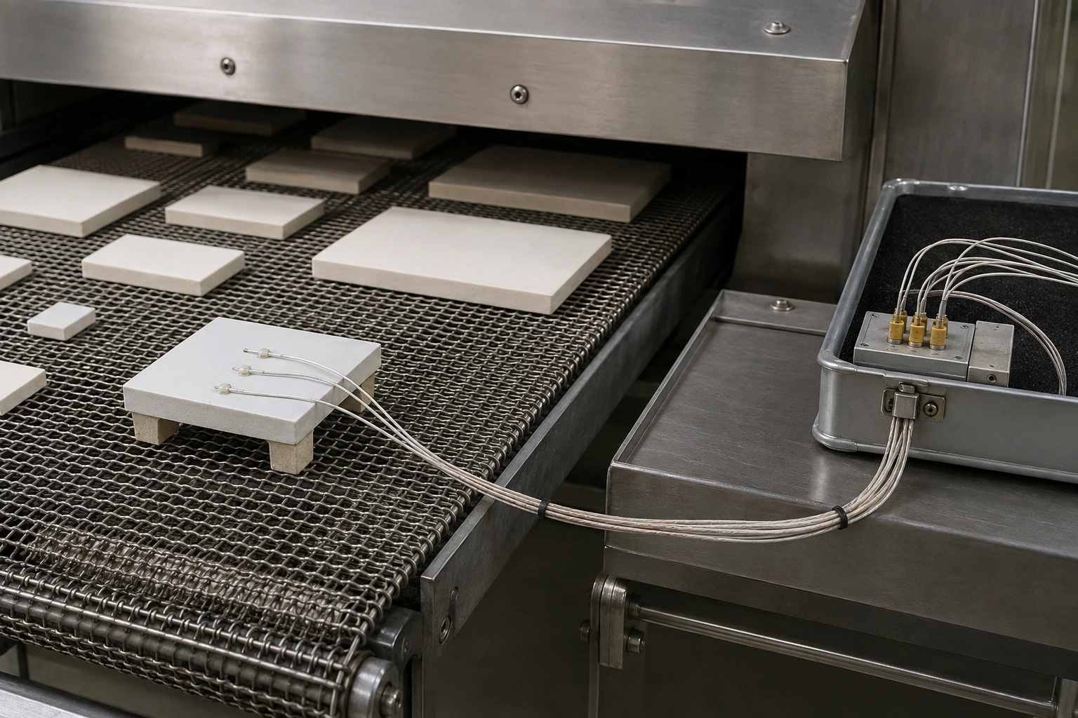
A fixed control thermocouple senses its installed furnace location. A traveling probe records its own response along the conveyor. A probe attached to a carrier is influenced by that carrier, and a probe attached to a ceramic panel is intended to follow a particular part location. Those traces answer related but different questions and should not share an ambiguous label such as furnace temperature.
Retain the sensor position, attachment and object identity for each channel. An apparently repeatable free-probe peak does not prove that a thick panel center reached the same temperature at the same time. Conversely, a slow part-attached response may be caused partly by the attachment rather than the panel itself. The measurement description is essential to interpreting any loaded-versus-unloaded difference.
Describe loading as a thermal arrangement, not only a part count
Record panel material, thickness, dimensions, printed coverage, carrier or setter, spacing and position across the belt. Two loads containing the same number of parts can expose different surface areas and place different thermal mass in each region. A different carrier can change both the energy needed to heat the load and the contact path beneath the panel.
Identify whether the comparison represents an isolated panel, the leading edge of a load, steady running or a gap followed by renewed loading. The furnace may respond differently across those conditions. Do not assume heavier loading always changes every channel in one direction; radiation, airflow, support and control response interact. Measure the actual arrangement that the proposed process needs to tolerate.
Control thermocouple attachment before comparing profiles
The junction must couple adequately to the intended surface without adding an excessive local thermal disturbance. Junction size, contact condition, wire routing and attachment material can change the recorded response. A wire exposed differently to radiation can also influence the reading through the junction and its surroundings. Inspect the attachment before and after the run for movement or degradation.
Use an attachment method compatible with the ceramic, printed layers, atmosphere and full temperature range. A solder or tape method described for a PCB reflow application is not automatically suitable for ceramic thick film firing. Select the sensor, insulation and protective arrangement for the actual process, and verify repeatability with the intended attachment rather than relying on a generic profiling accessory.
Separate equipment repeatability from the effect of loading
A useful comparison preserves a common measurement arrangement while changing the load deliberately. Repeat selected conditions to reveal drift over time. Do not compare a new part-mounted probe under load with an old free-probe trace and attribute the entire difference to thermal mass.
| Comparison | Question it answers | Important limitation |
|---|---|---|
| Same traveling probe on repeated passes | Does the measurement arrangement reproduce itself? | Does not establish part temperature |
| Same instrumented panel alone and in representative loading | How does the surrounding load affect this panel location? | Requires unchanged attachment and support |
| Equivalent panel locations across the belt | Is there a positional exposure difference? | Sensors and attachments must be comparable |
| Load start, steady running and restart after a gap | Does the process remain suitable through transitions? | One stable pass cannot represent every transition |
| Same load before and after a carrier change | Does the new support alter the exposure? | Must retain part geometry and process conditions |
Compare material-relevant time intervals as well as peaks
Use the selected paste system to define which intervals need review: drying or organic removal, high-temperature development of the functional film and cooling may impose different constraints. Compare heating rate, time in the relevant temperature window, peak and cooling behavior for each channel. A similar peak can conceal a materially different duration or earlier heating history.
For constant conveyor speed, geometric residence time in a known zone is its effective length divided by speed. That calculation locates the part in the furnace, but it is not the time the part spends above a material threshold. Determine threshold exposure from the measured part trace with a stated sampling interval and crossing rule. Avoid reporting more time precision than the measurement can support.
tzone = Lzone / vbelt
- tzone: geometric residence time in the defined furnace region
- Lzone: effective travel length of that region
- vbelt: measured constant conveyor speed
Constant speed and a defined spatial region. The equation does not predict part temperature, heating lag or time above a material-specific threshold.
Investigate trace anomalies before changing the recipe
A sudden discontinuity in one channel can indicate a loose junction, damaged wire or connection problem. A consistent difference among locations may be real, but first compare attachment condition and specimen construction. Record which channel experienced a physical change during the pass, and do not smooth away a spike that may explain why the result is unreliable.
If a part-mounted trace changes after repeated profiling of the same specimen, review whether the specimen or attachment has changed with thermal cycling. Printed coverage and surface condition can evolve, so an indefinitely reused profile panel is not automatically representative of fresh production. Keep a defined service history and replacement criterion for the instrumented assembly used in comparisons.
Link the thermal comparison to the printed layer's outcome
A trace inside a proposed temperature window is necessary evidence for that thermal condition, but the functional film still needs its own checks. Compare resistance, continuity, adhesion-related observations or dielectric behavior appropriate to the layer using specimens linked to the same loading and process history. A furnace graph cannot substitute for those material and circuit results.
When a loading change alters both the profile and the electrical result, preserve other process inputs before making a causal claim. Paste state, deposited thickness or another firing pass may have changed at the same time. A controlled comparison should connect the observed thermal difference to a repeatable product response, rather than attributing every resistance shift to the nearest visible change in the graph.
Release the loading window with the profile record
The transferable result includes the furnace recipe, measured conveyor speed, allowed load arrangement, carrier identity, sensor map and acceptable exposure criteria. State whether start-up, restart and sparse loading are included or require separate handling. This is more reproducible than issuing only zone setpoints and assuming the production team will recreate the measurement conditions.
Recheck the relevant comparison after changes in panel format, support, loading density, printed material system or furnace condition. Profiling equipment must remain within its thermal and mechanical ratings, with approved handling and recovery procedures. The goal is a demonstrated part-exposure window for the intended route, not an unsupported claim that every position in a furnace matches its display exactly.
Send the loaded-profile comparison
Provide enough detail to distinguish an equipment survey from the exposure of the actual ceramic panel.
- Panel and carrier materials, dimensions, thicknesses, printed coverage, spacing and belt-position map.
- Furnace zone settings, measured conveyor speed, atmosphere and run/load-transition condition.
- Sensor type, rated range, channel locations, attachment method and pre/post-run attachment observations.
- Individual time-temperature traces, material-processing criteria and linked electrical or physical results.
The drawing-upload form loads as you reach this section.