
On this page
The temperature displayed by a heater controller is the temperature reported by its sensing system, not automatically the hottest resistor or the useful load. Placement creates a spatial difference, attachment can create a thermal offset and sensor construction adds dynamic lag. These effects should be examined separately so a change in sensor position does not merely improve the displayed response while leaving the process temperature or local heater limit poorly observed.
Key design decisions
- Name the physical temperature that each sensor is intended to represent.
- Separate steady offset from dynamic lag using synchronized observations.
- Evaluate the sensor after installation, including adhesive, wires and surrounding airflow.
Define the temperature being controlled
Identify whether the process requires the temperature of a fluid, a contacting plate, a ceramic surface or another object. Then identify the temperature that limits the heater construction, such as the resistive region, dielectric or terminal joint. These may require different observation locations.
A sensor can serve a useful control purpose without measuring the maximum heater temperature. The design should state that relationship rather than leaving it implicit. Draw the sensor position relative to the active pattern, load contact and likely heat sinks. This makes it possible to evaluate whether a measured difference is a genuine physical gradient or an error in how the sensor represents its intended location.
Distinguish placement error from calibration error
A calibrated sensor can accurately report the wrong location for the process requirement. Heat flows from the resistor through the substrate and interface into the load, producing gradients along that path. A sensor near a cool support can therefore differ from a sensor in the active center even when both are functioning correctly.
Map the relevant gradient under the intended load and operating conditions. Do not correct a changing spatial difference with a fixed software offset unless the relationship has been shown to remain valid over the required range. A compensation derived at one flow rate or mounting condition may be wrong after the boundary changes. Calibration of the sensor itself does not remove that installation dependence.
Examine the sensor-to-surface heat path
The sensor exchanges heat with the target surface, its wires, its adhesive and surrounding air. Poor surface contact or a thick low-conductivity attachment can pull its temperature away from the intended surface value. The sensor’s own mass and shape also influence how much it disturbs a small heated region.
Specify attachment material, bondline, contact area and cable routing. Repeat selected measurements after remounting to assess installation repeatability. A sensor that gives consistent readings only when pressed manually against the surface does not yet have a controlled production attachment. Improving that interface may be more effective than changing controller settings.
Measure dynamic lag with a meaningful step
Sensor response time depends on the complete heat-transfer condition. A response value measured in a well-stirred bath cannot simply be assigned to the same element bonded to a heater through an adhesive. The installed sensor and the target may behave as multiple thermal nodes rather than one simple time constant.
Apply a controlled thermal or electrical change and compare the sensor with an independently characterized observation of the relevant surface or load. Use synchronized timing. A delayed rise, a delayed cooling response and a steady offset can point to different problems. Preserve the full traces instead of reporting only the time at which the controller display crosses the target.
For a first-order sensor model: τ_s dT_s/dt + T_s = T_target
- T_s: indicated sensing-element temperature in the simplified model.
- T_target: target temperature coupled to the sensor through the modeled attachment.
- τ_s: installed response constant under the stated boundary, not a universal sensor property.
The model neglects separate wire, adhesive and environmental heat paths. Use it only when the observed response supports an approximately first-order interpretation.
Use paired signals to identify the error type
Compare sensors and thermal observations at locations selected to separate geometry from attachment. Two sensors placed far apart do not isolate attachment error because a real gradient may exist between them. Two differently attached sensors near one region can be more informative, provided they do not materially alter the heat path.
Use both heating and cooling traces. An attachment problem may show a persistent offset toward ambient; a response delay may cause opposite apparent errors during rising and falling temperature. A load-to-heater gradient may instead track useful heat flow. The investigation should connect the signal behavior to the physical path before choosing a correction.
| Observed behavior | Question to investigate | Controlled comparison |
|---|---|---|
| Difference remains after the assembly settles | Spatial gradient, attachment heat leak or calibration offset. | Compare near-location observations and change only the attachment or heat path. |
| Sensor lags on heating and cooling but agrees after settling | Installed sensor response delay. | Measure a synchronized step with a faster characterized method. |
| Reading changes when wires are rerouted | Heat conduction through leads or electrical interference. | Control wire thermal anchoring and inspect the electrical measurement simultaneously. |
| Offset changes with fluid flow or mounting pressure | A real gradient in the heater-to-load path. | Measure the load interface and preserve the physical boundary in the comparison. |
Use infrared cross-checks with surface conditions controlled
Infrared imaging can help reveal spatial gradients without placing a sensor on every point, but emissivity and reflections must be handled correctly. Exposed metal, glaze and adhesive do not necessarily give comparable apparent temperatures. Spot size and viewing geometry also matter near a small sensor or trace.
Do not force camera settings to match a contact sensor before checking whether that sensor is itself influenced by attachment. Use a method appropriate to the material and instrument, and retain the settings. Agreement between two methods is useful only when their relevant error sources have been considered rather than adjusted until their displayed numbers coincide.
Relate sensing error to control behavior
A delayed sensor can allow the heater to continue receiving high power after the target surface has already approached its limit. A sensor near the heat source may react quickly but regulate a temperature different from the useful load. The controller must be reviewed against that physical relationship, not tuned in isolation from it.
Keep protective sensing requirements separate from normal process control. A sensor position chosen for stable regulation may not cover every local abnormal hot region. The equipment design should determine the required observation and interruption strategy. The heater review should provide the measured gradients and delays that make that decision possible.
Lock the installed sensing arrangement
Include sensor coordinates, orientation, attachment material, wire path and any thermal anchoring in the assembly instructions. Record the associated response and offset observations at the relevant load conditions. If production assembly cannot reproduce the laboratory attachment, the measured performance will not reliably transfer.
Reassess sensing after changes in substrate thickness, adhesive, load contact, cable route or enclosure airflow. Even an unchanged sensor part number can give a different installed response. Keeping the physical sensing arrangement controlled prevents repeated controller retuning from becoming a substitute for a stable thermal measurement.
Send the sensing geometry and synchronized traces
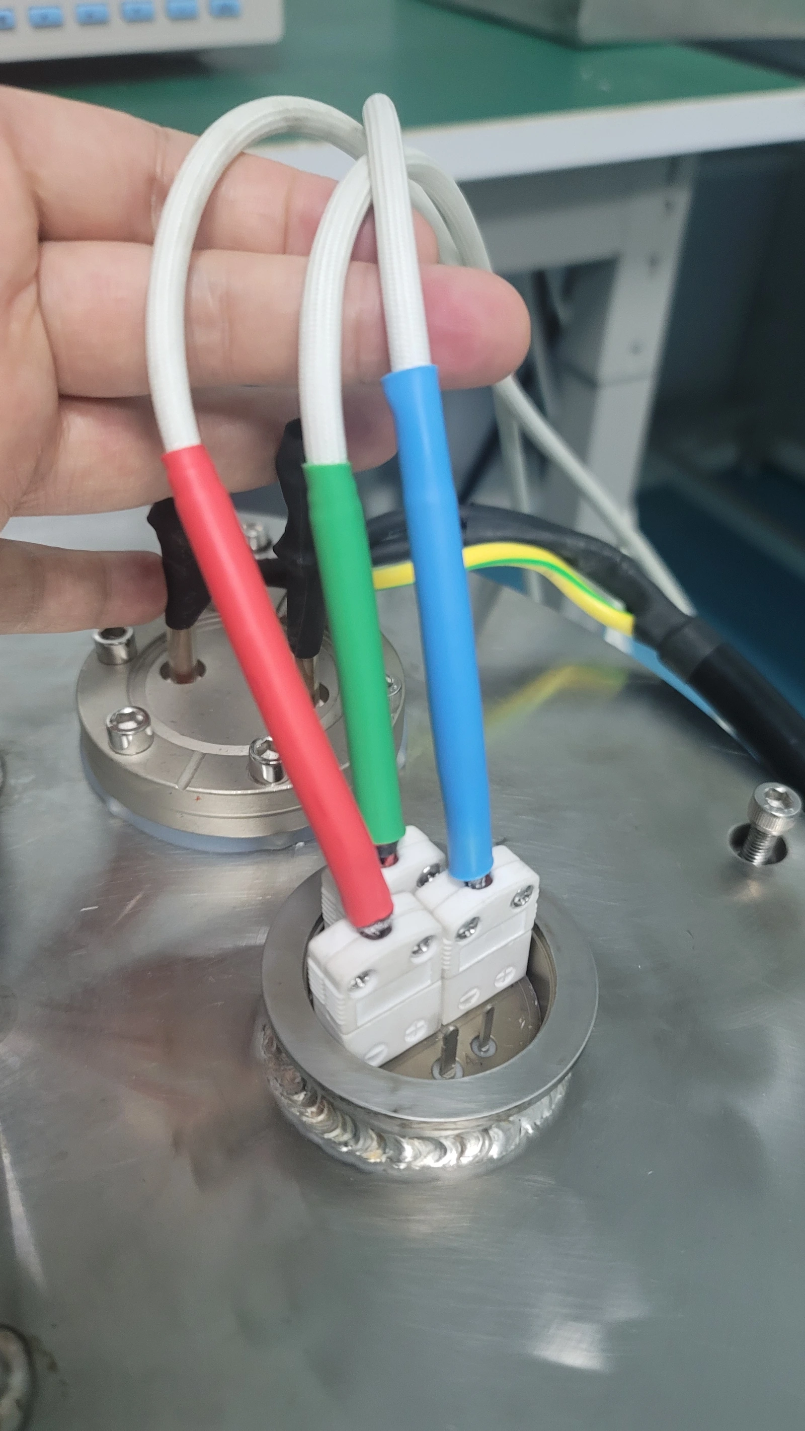
A sensor-interface review should show the intended measured temperature and the complete installed attachment.
- Heater, load and sensor coordinates with the active pattern, contact surfaces, supports and local temperature limits.
- Sensor construction, calibration information, attachment material and thickness, cable route and thermal anchoring.
- Power-step or process-change records containing synchronized heater, load, sensor and electrical input observations.
- Required control accuracy and response, operating load range, proposed compensation and separate protective-sensing requirements.
The drawing-upload form loads as you reach this section.