
On this page
A heat spreader can reduce temperature differences between a patterned heater and a wider load, but it also adds thermal mass and new interfaces. Thickness is therefore a design variable rather than an automatic route to better performance. The review should identify the distance over which heat must spread, the area through which it enters and leaves, and the warm-up or cooldown response that the process can tolerate.
Key design decisions
- Define the heat-source area and useful load area independently.
- Compare lateral spreading, through-thickness resistance and added thermal capacity.
- Control contact quality before attributing an improvement to spreader thickness.
Draw the source and sink areas
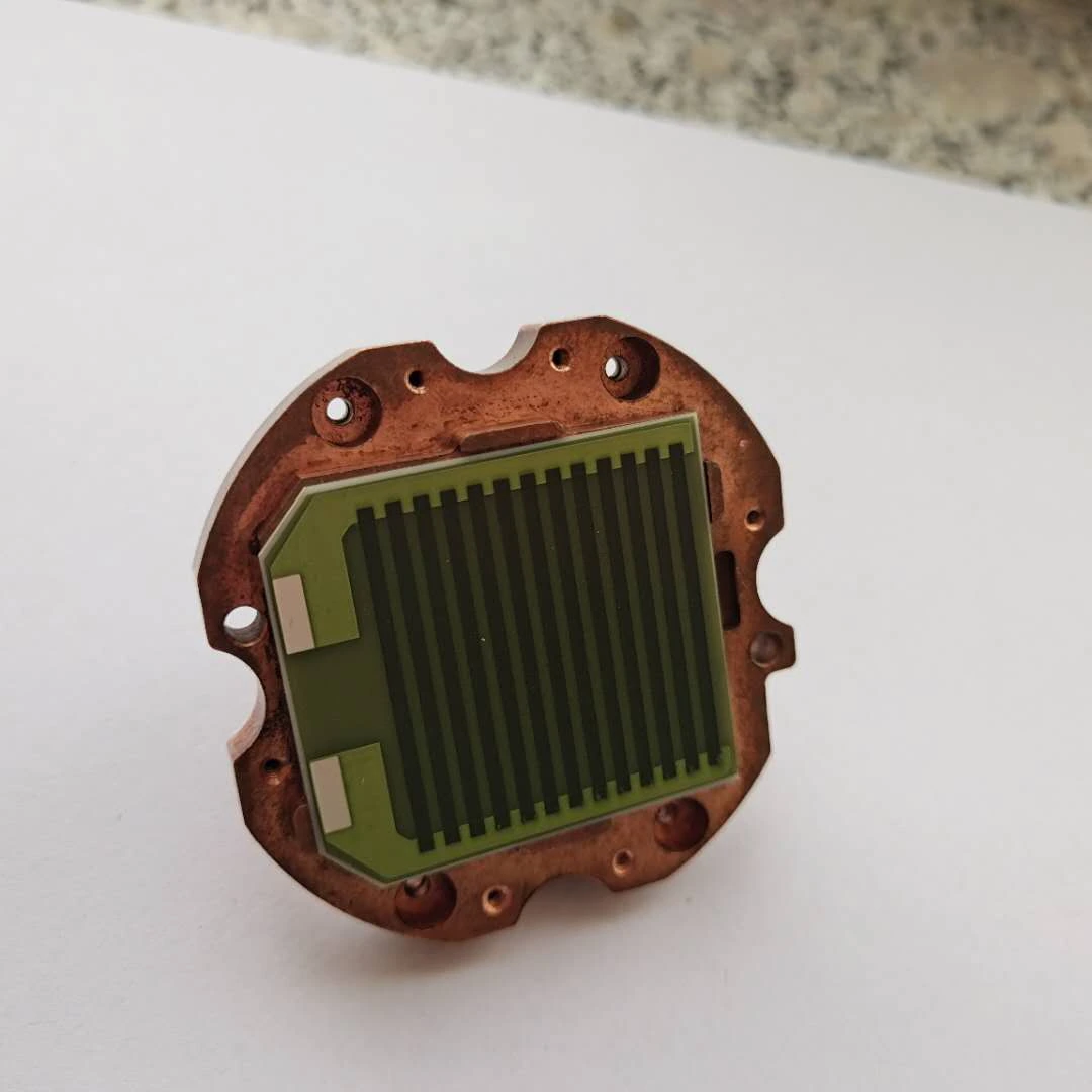
Mark where heat enters the spreader from the printed heater and where useful heat leaves into the load. The areas may be similar, partially overlapping or very different in size. Include supports and exposed surfaces that remove heat without serving the process.
A spreader is most useful when it addresses a specific mismatch between those areas or smooths a known spatial generation pattern. If the source already covers the load with good contact, adding a thick plate may contribute little useful spreading while increasing stored energy. Start with the actual spatial problem instead of selecting material and thickness from a general conductivity comparison.
Understand the two directions of heat flow
Increasing thickness changes the cross-section available for lateral conduction and the distance for heat crossing the thickness. It also changes mechanical stiffness and may improve or worsen the contact formed under a given mounting arrangement. These effects can act in different directions, so a single thermal-resistance expression is rarely enough for the entire assembly.
Use a geometry-appropriate model to compare a few realistic thicknesses. Inspect the temperature distribution and useful load response rather than only one point. If a one-dimensional model is used for an interface or layer, state which path it represents. Do not interpret that simplified value as the complete spreading behavior of a wide plate with a small heat source.
Calculate the energy penalty of added material
The spreader must usually warm along with the load. Its added thermal capacity follows from its mass and heat capacity over the operating interval. At limited available power, this increases startup energy and can extend warm-up time. Stored heat can also affect cooldown and temperature rise after power is reduced.
Determine how much of the spreader participates during the process interval. A large plate may not become uniform immediately, so a distributed model can be needed for short transients. The useful comparison reports both the reduction in spatial temperature difference and the change in response. A smoother final map is not necessarily an improvement if the equipment can no longer meet its timing requirement.
C_spreader ≈ ρ_m A t c_p; E_warm ≈ C_spreader ΔT
- ρ_m: spreader material density in kilograms per cubic meter.
- A and t: spreader plan area and thickness in consistent SI units.
- c_p: heat capacity appropriate to the temperature interval.
This estimate treats the spreader as a uniformly heated mass for the energy calculation. Short-time spatial response and temperature-dependent properties may require a distributed model.
Keep the interface from controlling the comparison
The heater-to-spreader and spreader-to-load interfaces can dominate temperature differences. Bondline thickness, flatness, contact pressure and trapped air should be controlled when comparing spreader candidates. Otherwise a thicker or more expensive material can appear better simply because it happened to make better contact.
Measure temperatures on both sides of important interfaces where practical. Repeat the assembly to determine contact variability. If interface temperature drop is much larger than the gradient within the spreader, improving contact may be the most effective next action. The assembly procedure should be treated as part of the design rather than an unrecorded laboratory technique.
Compare architectures with a common operating objective
Hold the useful load, target temperature, initial condition and mounting boundary constant when comparing thickness or material. Report the actual electrical input because a controller may supply different power to maintain the same load temperature. A fixed-power test and a regulated-load test answer different questions.
Choose the comparison that fits the decision. Fixed power can reveal how heat paths and mass change response. Regulated load can reveal the power required and the resulting heater temperature. Both may be useful, but do not combine the best feature from each into one unsupported performance claim.
| Design change | Potential benefit | Cost or risk to evaluate |
|---|---|---|
| Increase spreader thickness | More section for lateral heat flow and potentially greater stiffness. | Added thermal mass, altered through-thickness path and changed mounting load. |
| Increase load-contact area | Broader useful heat-transfer boundary. | Additional flatness and interface control across the larger region. |
| Choose a higher-conductivity material | Reduced internal gradients in an appropriate geometry. | Material-specific mechanical, electrical, joining and temperature constraints. |
| Reduce bondline resistance | Lower temperature difference between heater and spreader. | Assembly repeatability, stress accommodation and compatibility of the interface material. |
Measure transient and spatial behavior together
Place observations at the heat-entry region, spreader center and edges, useful load and important supports. During startup, record how the spatial gradient evolves rather than assuming the final profile exists from the beginning. During shutdown, observe stored heat moving from the spreader into the load or terminal region.
Use a measurement method that does not conceal local interface problems. A large sensor can average a small hot region, and a surface coating added for infrared measurement can change the boundary. Document those effects. The final comparison should make it possible to identify whether an improvement came from spreading, contact, power modulation or changed environmental loss.
Select material from the complete functional requirement
Conductivity matters, but the spreader may also need to provide electrical isolation, accommodate thermal expansion, resist the environment or support a joining process. A ceramic and a metal plate cannot be substituted solely on conductivity without examining those functions. Use the actual material grade and temperature-dependent information where it affects the design.
Consider which surface must remain electrically isolated and whether the interface materials provide that function. A mechanically stiff plate may constrain a thin heater or ceramic more strongly during temperature changes. The preferred material is the one that meets the coupled thermal, electrical and mechanical requirements in the actual construction.
Specify the spreader and attachment as one assembly
The design package should state spreader material, thickness, flatness, source and load contact areas, interface materials and the assembly sequence. Include the measured warm-up, cooldown and useful-zone temperature results at the intended operating conditions. This prevents a later substitution from retaining only the convenient part of the specification.
If the load area, power pattern or mounting changes, revisit the spreading model. A thickness selected for one source-to-load area ratio may not be appropriate for another. Keep the final choice tied to the original spatial and timing objectives so the review remains understandable throughout product development.
Send the source-to-load thermal layout
A spreader review needs the areas and timing constraints that define the thermal architecture.
- Heater active area, spreader dimensions and useful load-contact area, with all supports and unintended heat sinks identified.
- Candidate materials and thicknesses, available property data, flatness and electrical-isolation requirements.
- Initial and target temperatures, allowed warm-up and cooldown time, supply limits and the intended control variable.
- Interface materials and assembly method, paired temperature records across contacts and spatial maps during startup and steady operation.
The drawing-upload form loads as you reach this section.