
On this page
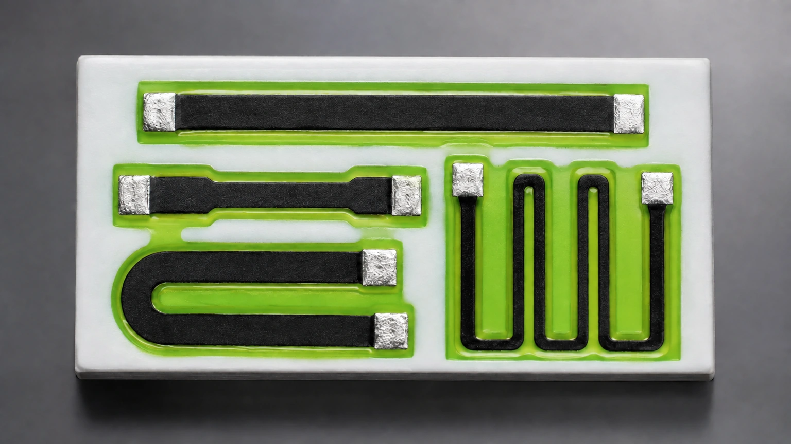
A printed film does not have to be a long rectangular strip to support a sheet-resistance measurement. A dedicated coupon with four small perimeter contacts can use a different current-distribution model. The useful result depends on satisfying that model's geometry and material conditions, not merely connecting four wires to an arbitrary finished circuit.
Key design decisions
- Separate the dedicated continuous-film coupon from a patterned resistor network with holes, terminations and branches.
- Retain both characteristic resistances and the contact-switching map before calculating sheet resistance.
- Check geometry and measurement consistency independently of numerical convergence.
1. Choose a material-monitor coupon, not a finished resistor substitute
A rectangular resistor's number-of-squares calculation starts from its effective current-path dimensions. A van der Pauw coupon instead infers sheet resistance from boundary measurements around a continuous film. These methods answer related material questions but use different electrical boundaries. Do not enter the two-terminal resistance of a finished trimmed resistor into the perimeter-contact equation.
Use a dedicated coupon when the task is to compare the processed film under a reproducible measurement geometry. Keep its material, substrate and thermal history connected to the product it monitors. The resulting sheet resistance does not include the product's particular termination overlap, trim cut, corner field or local power distribution. Those remain part of the finished resistor design and inspection.
2. Check the conducting domain before checking the arithmetic
The basic model assumes a thin, uniform, isotropic conducting sheet that is simply connected, with four very small ohmic contacts on its perimeter. A hole through the conducting region or a nonconducting island violates the simple domain assumption. A continuous outline in a photograph is insufficient if the film contains an electrical interruption.
For a fired composite, the sheet description is an effective continuum approximation at the coupon scale. It does not require pretending the microscopic material is chemically homogeneous. However, macroscopic thickness gradients, disconnected areas or directional conduction can undermine a single scalar sheet-resistance interpretation. Establish the coupon's suitability at the intended spatial scale rather than transferring assumptions from a uniform semiconductor wafer without review.
3. Identify two independent boundary configurations
Label contacts one through four in a stated cyclic order around the coupon. In one configuration, inject current at contact one, remove it at two and sense the voltage between four and three with the sign convention defined. Rotate the source and sense pairs to obtain the second configuration. Save the actual contact map beside the readings.
The positive characteristic resistances RA and RB are voltage-to-current ratios for these two arrangements after justified consistency checks and averaging. They need not be equal merely because the film is uniform: coupon shape and contact placement influence them. Their difference therefore must not be reported directly as material anisotropy. Conversely, matching values do not establish that the contacts are small or that every point in the film is uniform.
4. Solve the sheet-resistance equation, not the average reading
For positive RA and RB, the exponential equation has one positive sheet-resistance solution. As the trial sheet resistance approaches zero the exponential sum approaches zero; as it grows without bound the sum approaches two. The sum increases continuously, which permits a bracketed numerical solution without inventing a geometry factor.
When both characteristic resistances are 100 ohms, symmetry reduces the equation to twice one exponential equal to one. Sheet resistance is therefore 100π divided by ln2, approximately 453.236 ohms per square. It is neither 100 ohms per square nor the resistance of one visible square measured between full-width end electrodes.
exp(−πRA/Rs) + exp(−πRB/Rs) = 1; if RA = RB = R, Rs = πR/ln2
- RA and RB are positive characteristic transfer resistances in Ω from the defined contact configurations.
- Rs is the model-derived sheet resistance, conventionally reported in Ω/□.
- The exponential arguments are dimensionless; π and ln2 are dimensionless constants.
Thin uniform isotropic simply connected sheet with sufficiently small ohmic perimeter contacts, negligible measurement loading and a stable ohmic test condition.
5. Check an unequal-reading example by substitution
Assume RA is 100 ohms and RB is 200 ohms. Let x equal exp of negative 100π divided by Rs. The second exponential is then x squared, so the equation becomes x plus x squared equals one. Its physically admissible root is approximately 0.618034, giving Rs approximately 652.850 ohms per square.
A shortcut that averages the readings to 150 ohms and applies the equal-reading factor would report approximately 679.854 ohms per square, about 4.14 percent above the proper result. Substituting 652.850 into the two exponentials yields approximately 0.618034 and 0.381966, whose sum is one. This numerical check tests implementation, not the physical validity of the coupon.
For other unequal pairs, retain the solver bracket, convergence rule and equation residual. Tight numerical tolerance cannot compensate for uncertain currents, offsets or unsuitable contact geometry. Report enough precision to reproduce the calculation while rounding the interpreted result consistently with the experimental uncertainty.
6. Keep measurement checks outside the solver
Repeat suitable current reversals and reciprocal source/sense arrangements with a consistent voltage sign convention. Compare them before reducing the data to RA and RB. The redundant readings expose inconsistency that would disappear if a spreadsheet accepted only two pre-averaged numbers.
Establish acceptable differences from the measurement uncertainty and intended decision. Do not import a percentage acceptance band from an unrelated sample procedure. Check contact linearity over the chosen current range, settling after switching and temperature stability. Probe damage near the perimeter can change the conducting domain. A successful root finder still returns a number when such physical problems make the input pair unsuitable.
7. Resolve common coupon departures explicitly
The method's freedom from an exact rectangular outline is not freedom from all geometry constraints. Select a follow-up that addresses the violated assumption rather than attaching a generic correction percentage.
| Condition | Why the basic result is limited | Useful next action |
|---|---|---|
| Large or inward-positioned contacts | The assumed point-like perimeter boundary is changed | Evaluate a supported finite-contact model or revise the coupon |
| Hole, disconnected patch or patterned island | The simple conducting domain no longer applies | Use a dedicated continuous coupon or a suitable field model |
| Macroscopic thickness gradient | One uniform sheet parameter may not describe the specimen | Map the layer and test a uniformity hypothesis |
| Reciprocal or reversal readings disagree | The reduced pair hides electrical or temporal inconsistency | Retain individual readings and investigate before averaging |
| A product has different terminations or trim cuts | The coupon excludes product-specific current paths | Apply separate product geometry and electrical checks |
8. Keep sheet resistance distinct from bulk resistivity
Multiplying a valid sheet resistance by a representative uniform conducting thickness gives an effective resistivity in consistent units. A 652.850-ohm-per-square sheet at an assumed 10 micrometre thickness gives approximately 0.00652850 ohm-metre. Thickness uncertainty and its spatial representativeness enter that conversion even when the electrical solution is precise.
Do not use the substrate thickness, a dried precursor thickness or a nearby protective coating thickness for this calculation. If the fired film lacks a defensible uniform thickness, retain the sheet result with its method boundary rather than reporting an apparently intrinsic resistivity. A comparison across process lots should preserve coupon layout, contact formation, measuring conditions and the relation between coupon and product firing history.
Review a four-contact printed-film coupon
Provide the complete conducting outline and raw switching record before assigning a sheet-resistance value.
- Continuous film outline, any holes or isolated areas, contact coordinates, sizes and cyclic numbering.
- Film and substrate identity, print/firing history, local thickness observations and coupon-to-product relationship.
- Individual current/voltage readings, sign convention, reciprocal and reversal checks, settling and temperature.
- Computed RA and RB, solver result and residual, uncertainty basis and intended material or product decision.
The drawing-upload form loads as you reach this section.