
On this page
A changing sensor output after repeated motion does not identify which member of the contact pair has changed. The track may wear, the wiper may change shape, material may transfer between them or debris may alter contact. A useful wear record follows both members and preserves their pairing. Controlled replacement comparisons can then test specific explanations, provided their effects on force, alignment and surface condition are recorded.
Key design decisions
- Retain original paired electrical and physical observations before cleaning or replacing either member.
- Compare total-track behavior with moving-wiper behavior so body change and contact change are not conflated.
- Treat a new-wiper comparison as a controlled diagnostic experiment, not proof that the old track is unchanged.
Establish an identifiable baseline for both surfaces
Give the card and wiper separate identifiers and record their initial pairing. Photograph the same track regions and contact features before motion begins, using sufficient detail to compare later observations. Include contact force, mounting geometry and electrical loading with the baseline curve.
A photograph of the card alone cannot establish the initial wiper condition. Record contact-finger shape and footprint where observable, and preserve any assembly adjustment. If the first electrical measurement already includes a running-in sequence, state that exposure. Otherwise, the earliest physical change can disappear into an undocumented preparation step and later comparisons will use an ambiguous starting condition.
Measure total-track and wiper-dependent quantities separately
Where the circuit permits, measure end-to-end track resistance independently of the moving contact. Then measure the output through the wiper under the specified receiver load. A stable total-track value with worsening moving output suggests a different problem from a substantial change in the body resistance, although neither observation alone identifies the exact mechanism.
Record local curve error, interruptions and noise with travel position and direction. A single average resistance or one peak-noise value can hide a localized worn region. Preserve the raw signal bandwidth and filtering definition. Define current, travel speed, evaluated electrical travel and acquisition bandwidth when reporting contact-resistance variation.
Relate the observed region to its actual motion exposure
Not every part of a track experiences the same sliding history. Repeated motion around one operating point can concentrate wear there, while a full sweep distributes travel differently. Record endpoints, dwell, speed and reversals, and map the contact path onto the photographs.
Use cumulative sliding distance where it clarifies comparison, but keep motion profile and cycle definition. A contact reversing repeatedly over a short region can behave differently from one accumulating the same distance over a long path. If a visible change appears outside the intended path, investigate lateral motion, mounting shift or debris movement before attributing it to the nominal test exposure.
Make photographs comparable enough to support interpretation
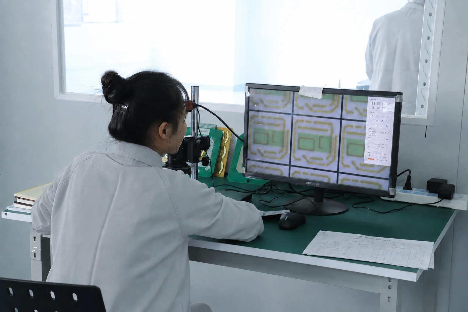
Use consistent lighting, view angle, magnification and focus. Record scale and the location relative to card datums. A darker region may reflect transfer, contamination, surface texture or lighting; color change alone does not quantify material loss. Where loss depth matters, use an appropriate measurement method with its own uncertainty.
Capture the original state before cleaning. If cleaning is part of a diagnostic sequence, document the method and photograph afterward as a separate condition. Cleaning may remove debris or transferred material and change the electrical result. The before-and-after difference is useful evidence, but it cannot replace the original as-run condition in the wear record.
Use member substitutions to test the competing causes
A replacement study is most informative when it includes the original used pair and suitable reference members. Keep force, alignment, receiver and motion conditions consistent, and record any unavoidable change caused by disassembly. Avoid using a visibly damaged reference surface for the comparison.
| Pairing | Question tested | Interpretation limit |
|---|---|---|
| Used track with its original used wiper | What behavior developed in the original system? | Contains both member changes and their interaction |
| Used track with a characterized new wiper | Does changing the wiper improve output? | New contact alignment or debris redistribution may also contribute |
| Reference track with the used wiper | Does the wiper carry the discrepancy to another track? | Reference geometry and surface must be suitably comparable |
| Reference track with a characterized new wiper | What is the comparison baseline? | Does not reproduce the used pair's surface history |
| Original pair after documented cleaning | How much behavior depends on removable surface material? | Cleaning can change the surface and does not identify every mechanism |
Compare changes at the same positions and conditions
Calculate signed change from the baseline at fixed coordinates, along with any shift in the curve's mechanical index. If the card was remounted between stages, a horizontal shift can masquerade as local resistance change. Check the datum alignment before interpreting the difference plot.
For a hypothetical local slope of three ohms per degree, a remount offset of 0.1 degree produces approximately 0.3 ohm of apparent change. Compare that scale with the observed wear-related difference. This simple calculation can prevent an alignment error from being assigned to track loss. Retain uncertainty and repeat measurements where the difference is close to the method's resolution.
ΔRobserved(x) = Rstage(x) − Rbaseline(x)
- Both curves use the same mechanical coordinate x and electrical boundary.
- Rstage is measured at the named exposure stage.
- The difference includes any unresolved alignment, contact and measurement contributions.
Excitation, receiver loading, temperature and coordinate alignment are sufficiently comparable for the intended interpretation.
Use combined evidence before assigning a wear mechanism
If a used wiper reproduces the discrepancy on a reference track and a new wiper improves the used track, the evidence supports a wiper contribution. It still does not prove the track experienced no change. If neither substitution restores behavior, both members or their interaction may matter, or the fixture condition may have shifted.
Link electrical trends with the physical location of contact and observed surface changes. Investigate contradictory results instead of forcing them into a single explanation. A stable total resistance with severe local output interruptions can be entirely plausible because continuity through the moving contact and conduction between fixed terminals are different measurements.
Report observed exposure rather than inventing service life
State the exposure completed, the acceptance criteria applied and the condition of both members at the final observation. If the test ended before a defined failure, report that outcome without extrapolating an unmeasured lifetime. If a failure occurred, preserve its detection criterion and the interval in which it developed.
For quotation, provide the intended motion distribution, environment and electrical interface along with available staged data. The wear review can then identify a relevant comparison or material-interface question. A replacement experiment is a diagnostic tool within that process; it cannot by itself establish universal durability for the track, wiper or complete sensor assembly.
Send the paired wear history
Provide both member records so changing output can be evaluated against the actual contact history.
- Card and wiper identities with initial pairing, force and alignment.
- Motion profile, cycle definition, cumulative travel and environmental condition.
- Total-track and wiper-output measurements with position and acquisition settings.
- Comparable staged photographs taken before cleaning or replacement.
- Replacement-pair and cleaning comparisons with all altered conditions recorded.
The drawing-upload form loads as you reach this section.