
On this page
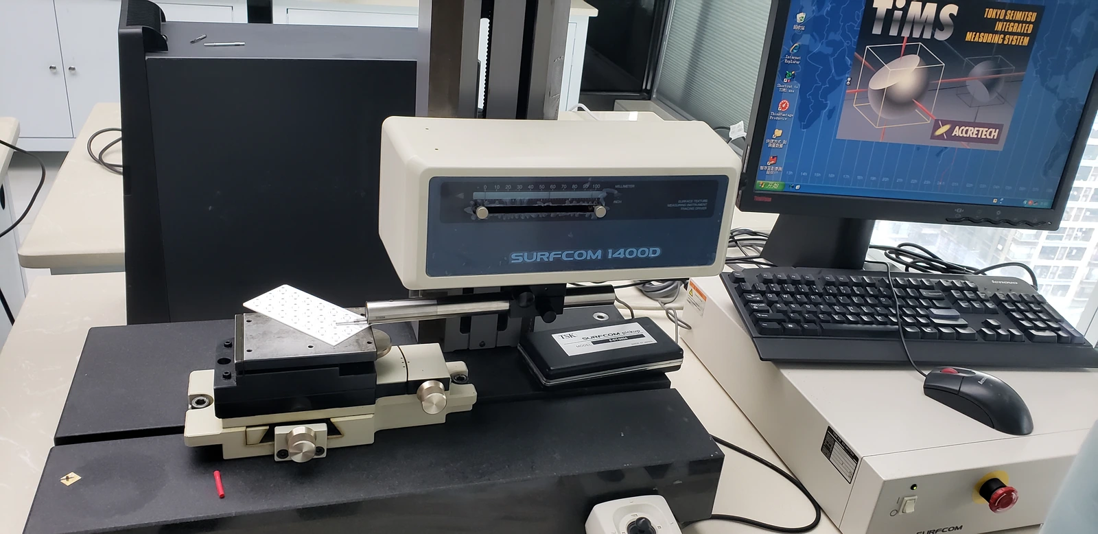
Surface profilometry can measure a printed-film step, describe local texture or reveal substrate shape, but these are different measurement tasks. A profile that is suitable for roughness is not automatically suitable for film thickness. The method must define the feature, scan path, baseline and processing settings before a numerical result can be compared across specimens.
Key design decisions
- Choose step height, roughness or form as the measurand before scanning.
- Preserve the unfiltered profile and the baseline-selection method.
- Match probe geometry and scan direction to the printed feature and material state.
Decide which geometric quantity is needed
For a printed resistor or conductor, the engineering question may concern film thickness above the substrate, local surface texture, edge shape or overall plate bow. Each requires a different sampling and analysis strategy. A roughness parameter calculated from a leveled trace does not directly report the height of the film above the ceramic.
Write the quantity on the inspection drawing, including the location and direction. If step height is required, identify the two surfaces being compared and whether they are both accessible. A glass overglaze covering the resistor changes the exposed surface; scanning its top does not directly measure the thickness of the hidden resistive film.
Preserve the surface state being evaluated
Record whether the specimen is dried, fired, cured, glazed, trimmed or assembled. The surface and mechanical robustness can differ between these stages. Handle it so that fingerprints, dust or loose particles do not become part of the measured texture. If cleaning is required by the method, document the process and ensure that it does not change the feature under investigation.
Support the specimen without forcing it into an unintended shape. A thin or flexible sample can deflect under mounting or probe contact, while a ceramic plate supported at uneven points can tilt. For a form measurement, support conditions are part of the measurand; for a local step, they still affect leveling and repeatability.
Select probe geometry and interaction
A contact stylus has a finite tip radius and applied force. It cannot follow a narrow valley or sharp corner exactly when the feature is smaller than the accessible tip geometry. On a soft or incompletely processed film, the stylus can also disturb the surface. Select settings appropriate to the actual material state and feature scale.
Inspect repeat scans for evidence that the measurement changes the surface. Where an optical method is considered, assess its response to reflectivity, transparency and steep edges rather than assuming that noncontact measurement removes all limitations. Use a method comparison or an independent section when the result depends on a feature that one probe cannot resolve reliably.
Choose a scan path that crosses the relevant feature
For a film step, cross the edge with sufficient length on the substrate and on the film to establish representative levels away from the transition. A scan running nearly parallel to an irregular edge may combine edge wandering with height variation. Mark the path so that repeat measurements address the same geometric question.
For texture, consider the direction of printing marks or other directional structure. Profiles along and across a directional surface can differ. For plate form, use enough spatial coverage to characterize the required shape rather than extrapolating from one short trace. Record scan length, sampling interval, speed and position together with the instrument configuration.
Define leveling and step-height extraction
A specimen tilted relative to the instrument creates a slope that must be distinguished from the film step. Select baseline regions that represent the intended underlying surface, and exclude the transition only through a stated rule. Fitting a line across both the substrate and film can reduce the apparent step and produce a misleading result.
Choose how the film level is calculated when its top has texture or a sloping edge. Report representative plateau height, local maximum or another defined statistic according to the engineering requirement. Do not substitute the highest point for average film thickness without saying so. Retain the original profile so another analyst can inspect the selected regions.
| Question | Measurement design | Common interpretation error |
|---|---|---|
| Film step above ceramic | Cross-edge scan with separate baseline and film regions | Roughness value is reported as thickness |
| Surface texture of a processed layer | Defined direction, evaluation length and filter | A single peak is treated as representative texture |
| Printed-edge shape | Adequate tip access and spatial sampling | Probe rounding is mistaken for the true edge |
| Substrate bow or form | Appropriate support and broad spatial coverage | Local leveling removes the shape of interest |
| Buried resistor thickness under glaze | Method that accesses or resolves the buried interface | Exposed glaze height is assigned to the resistor |
Keep filtering consistent with the measurand
Filtering separates profile components by spatial scale. A cutoff chosen for roughness can remove longer-wavelength features that are important for waviness or form. Leveling and filtering are therefore analysis decisions, not neutral cosmetic improvements. Record the filter type, cutoff and evaluation length used for any reported texture parameter.
For step height, use an extraction method designed for the step and avoid applying a roughness workflow that distorts the transition or plateau. Compare raw and processed profiles when establishing the method. If two instruments report different values, first align their definitions and processing settings before concluding that one instrument is inaccurate.
Evaluate location and setup variation separately
Repeat selected scans without remounting to assess short-term measurement variation. Then remount or reposition the specimen using the documented method to assess setup sensitivity. Finally, sample different relevant locations to assess real spatial variation in the printed feature. These three sources should not be combined into an unexplained spread.
Use a suitable calibrated artifact and instrument checks for the measurement range. Calibration confirms aspects of the instrument response, but it does not validate an unsuitable scan path or baseline. Include uncertainty contributions that matter to the decision, such as probe access, leveling, surface variation and the selected plateau statistic.
Connect the profile to the electrical or assembly question
A thickness or texture difference becomes useful when it is related to the feature's function. Compare local profiles with resistance, print geometry, glaze coverage or contact behavior at the same location. A broad average profile can miss a narrow constriction that controls a resistor's hot spot. Conversely, an isolated high particle may not represent the normal film body.
The final record should include specimen stage, image of the scan location, raw profile, processing settings, selected regions, result and measurement variation. This allows a manufacturing comparison to distinguish a real process change from a changed analysis setting. Preserve that method when evaluating subsequent batches or material revisions.
Define a printed-film surface measurement
Provide the feature and its function so the scan, probe and processing method measure the intended geometry.
- Drawing or micrograph with the required step, texture or form location.
- Material stack and specimen processing stage, including overglaze coverage.
- Expected feature scale and accessible substrate or film regions.
- Instrument, probe, scan and filter settings used in existing measurements.
- Raw profiles, baseline selections and the electrical or assembly concern.
The drawing-upload form loads as you reach this section.