
On this page
A thermal shock test is defined by the exposure experienced by the specimen, not simply by the hot and cold setpoints on a chamber screen. Transfer time, chamber recovery, specimen response and dwell all influence the thermal gradients applied to a thick-film circuit or heater assembly. Selecting the method requires a clear link between the suspected failure mechanism and the measured temperature history.
Key design decisions
- Distinguish zone transfer, air recovery and specimen-temperature recovery.
- Select the exposure medium and fixture as part of the method.
- Document specimen temperatures and diagnostic endpoints alongside cycle count.
Define the mechanism the test should exercise
Identify whether the concern is substrate cracking, film or glaze damage, terminal-joint stress, interface separation or another specific change. The material stack and assembly constraints determine how rapid temperature changes create local strain. An unmounted ceramic coupon and a heater rigidly attached to a metal load may respond differently even when they share the same chamber program.
Connect the test objective with the intended use or qualification requirement. A method selected for material comparison can be useful without reproducing every field event, but its interpretation must remain tied to that comparison. Do not choose a severe-looking sequence solely to accumulate an impressive cycle count; establish what observation would answer the engineering question.
Separate the three different timing quantities
Transfer time describes movement or switching between thermal environments. Air recovery describes the chamber environment returning to its specified condition after the load is introduced. Specimen recovery describes the part itself reaching the required temperature condition. These quantities can differ substantially because the specimen has thermal mass and exchanges heat through its actual exposed surfaces.
Read the selected method's definitions carefully and implement its timing basis. Starting dwell when the basket moves is not equivalent to starting it when the specimen reaches a defined condition. Record the chamber and specimen traces with event markers so another reviewer can determine which portion of each cycle was spent at the intended exposure.
Choose the exposure medium deliberately
Air-to-air transfer, switched-air systems and liquid exposure can impose different heat-transfer conditions and introduce different interactions with the specimen. A liquid may contact exposed conductors, penetrate a joint region or affect a coating in a way that dry air does not. The choice must match the applicable method and the compatibility of the construction.
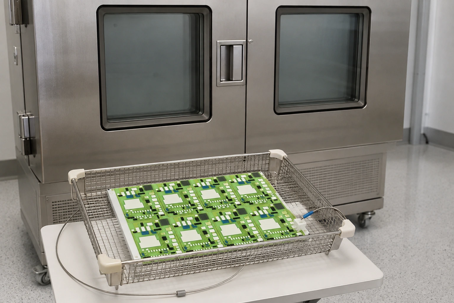
Do not describe a chamber with a fast programmed ramp as equivalent to every thermal shock method. Ramp rate, transition mechanism and specimen response must be compared using the required definitions. Likewise, an ordinary oven photograph or inventory listing does not establish the availability or performance of a thermal shock test setup.
Measure the actual specimen temperature
Instrument representative specimens at locations relevant to the thermal path. The center of a thick assembly can lag behind a thin edge, while a joint attached to a metal fixture can respond differently from the ceramic body. Sensor attachment and wires also influence local heat flow, so use a documented method that does not unnecessarily alter the response.
Measure with representative chamber loading and fixture mass. An empty-chamber performance trace does not establish the response of a fully loaded basket. Consider which specimen location is slowest to reach the required condition and which location experiences the steepest gradient. Both can matter, but they answer different questions.
| Recorded quantity | What it describes | What it does not establish alone |
|---|---|---|
| Transfer event and duration | Change between exposure zones or modes | Temperature reached by the specimen |
| Chamber-air recovery | Environmental response after the load arrives | Internal or worst-position specimen temperature |
| Specimen temperature trace | Thermal exposure at the sensor location | Temperature of every other layer or location |
| Dwell at the specified condition | Time maintained under the selected definition | Equivalent exposure under another method |
| Completed cycle count | Number of recorded sequence repetitions | Service life without a supporting mechanism model |
Control loading, orientation and support
Document specimen count, spacing, basket position, support points and orientation. Airflow access and thermal contact with the fixture can change local heating and cooling. If a specimen is clamped, specify how the clamp accommodates differential expansion. A fixture-induced crack is still important, but it must be distinguished from a failure of an unconstrained material specimen.
Keep electrical leads and sensor wires from becoming unintended supports or large heat sinks. If testing an assembled product, preserve the intended terminal strain relief and mounting boundary unless the selected method requires otherwise. Photograph the initial arrangement and record any changes during the sequence so differences between specimens can be interpreted.
Choose electrical and physical endpoints before testing
Measure a baseline at defined temperature and connection conditions. Depending on the objective, useful endpoints can include element resistance, continuity, insulation behavior, joint resistance and location-specific microscopy. The acceptance criteria and test settings must come from the applicable product and equipment requirements. A generic resistance percentage is not a universal pass criterion for every thick-film circuit.
Plan inspection intervals and how specimens will be handled between them. Cooling, drying or disconnecting a part can alter an intermittent symptom. Where a measurement is made outside the chamber, record the transfer and conditioning before the reading. Preserve the dynamic record when a failure occurs rather than relying only on a final room-temperature measurement.
Analyze changes at the relevant interface
Map observed damage to the stack and support drawing. A crack near a mounting feature, a terminal-joint change and a glaze defect can indicate different stress paths. Compare failed and unchanged locations, including the orientation relative to airflow and fixture contact. Use physical analysis that preserves the suspected feature before cleaning or sectioning.
Interpret the timing of the change as well as its final appearance. Damage emerging after an altered chamber load or fixture adjustment may reflect a changed exposure. If the result will be used to compare designs, keep the temperature histories equivalent or explain the difference. Identical setpoints are insufficient evidence of equivalent specimen stress.
Report the exposure rather than only the program
The report should include the selected method and revision, specimen construction, fixture, loading, environmental traces, specimen traces, transfer and dwell definitions, completed cycles and inspection results. Distinguish programmed values from measured ones. Include interruptions, defrost events or interventions that materially changed the exposure.
Use the outcome to decide the next design or process action. If the observed mechanism matches the concern, a controlled construction change can be evaluated under a comparable sequence. If it does not, revise the method or specimen configuration before extending the test. The useful result is a traceable link between thermal exposure and component behavior.
Select a thermal shock evaluation
Provide the construction, intended failure question and applicable method so specimen exposure and inspection can be defined consistently.
- Circuit or heater stack, substrate outline and terminal construction.
- Mounted or unmounted state and relevant service temperature events.
- Required test method, revision and acceptance criteria.
- Available chamber mode, fixture and representative load arrangement.
- Temperature instrumentation and baseline electrical or physical measurements.
The drawing-upload form loads as you reach this section.