
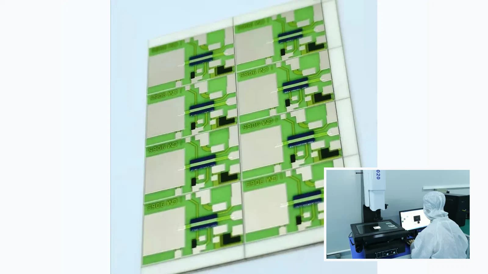
Overview
This engineering worksheet provides a bounded first-pass workflow for Printed Resistor Geometry Calculator. Output supports intake only; it does not replace material data, drawing review, prototype measurement, safety analysis, or application validation.
Project worksheet
Results are engineering estimates and remain bounded by the inputs and assumptions shown.
Use the worksheet with your drawing
Sheet resistance, geometry and independent worst-case bounds. Includes assumptions and a clearly marked arithmetic example.
Excel-compatible .xlsx · revision 9 September 2026. Inputs stay in your file. Estimates support engineering review and do not approve product performance.
Engineering review matrix
Each row links a design variable to evidence that can support a drawing or release decision.
| Variable | Control question | Verification route |
|---|---|---|
| Nominal function | For Printed Resistor Geometry Calculator, resistance, ratio, tolerance, TCR, voltage, power, pulse, and stability need a defined reference condition. | Measure value and ratio with stated probe geometry, temperature, dwell, and instrument conditions. |
| Geometry and sheet resistance | Paste sheet resistance and effective length-to-width set first-order value; corners and terminations disturb the ideal square model. | Correlate released artwork and processed-film measurements with actual resistance distribution. |
| Termination effects | Conductor overlap, current crowding, contact resistance, aspect ratio, and refire interactions can dominate short geometries. | Use Kelvin or controlled probing where termination resistance is material. |
| Loading and temperature | Power density, substrate spreading, terminal cooling, voltage coefficient, ambient, and duty determine self-heating and drift. | Verify resistance change and temperature field at the intended electrical and thermal boundary. |
| Trim and protection | Trim allowance, cut shape, measurement loop, stability margin, overglaze, and post-trim processing form one sequence. | Record pre-trim, target, post-trim, post-protection, and stability results against the released lot. |
Worksheet route
The order makes assumptions and ownership visible before a result is promoted to a requirement.
- 01
Enter known inputs
For Printed Resistor Geometry Calculator, complete enter known inputs against the controlled drawing, named assumptions, responsible owner, required evidence, and release decision.
- 02
Label assumptions and units
For Printed Resistor Geometry Calculator, complete label assumptions and units against the controlled drawing, named assumptions, responsible owner, required evidence, and release decision.
- 03
Review calculated relationships
For Printed Resistor Geometry Calculator, complete review calculated relationships against the controlled drawing, named assumptions, responsible owner, required evidence, and release decision.
- 04
Identify missing validation
For Printed Resistor Geometry Calculator, document the functional requirement, operating boundary, interfaces, quantities, and acceptance owner against the current drawing.
- 05
Attach output to the RFQ
For Printed Resistor Geometry Calculator, complete attach output to the rfq against the controlled drawing, named assumptions, responsible owner, required evidence, and release decision.
Failure controls
These are review prompts, not evidence that every risk applies or that every test is available.
- A
Value offset from geometry, thickness, firing, or termination interaction
- B
Local overheating and irreversible drift under load
- C
Trim-cut stress, current crowding, or inadequate stability margin
- D
Noise, voltage-coefficient error, humidity drift, or ratio mismatch
Inputs for a practical review
Unknown values may be labelled unknown. The review should convert uncertainty into an explicit decision or validation task.
Send Drawings- 01
Nominal resistance or ratio and complete tolerance budget
- 02
TCR, voltage, power, pulse, duty, and temperature range
- 03
Artwork, resistor dimensions, terminals, and trim keep-outs
- 04
Probe method, reference temperature, and acceptance method
- 05
Protection, environment, stability, and reliability profile