
On this page
- Wet Thickness Reflects Transfer
- Dried Thickness Reveals Solvent Removal
- Burnout Removes the Temporary Structure
- Firing Creates the Functional Thickness
- Measure Location and Topography
- A Worked Engineering Review
- Design Review Checklist
- Questions Engineers Commonly Ask
- Related Engineering Resources
- Closing Note
Prepared by Chipsimple Engineering Team, Engineering and technical content review
Published online August 10, 2026 · Reviewed August 10, 2026
ENGINEERING ARTICLE 15 / VOLUME 3
From Wet Print to Fired Film: Why Thickness Changes
Immediately after printing, the deposit contains a substantial organic vehicle. Drying removes volatile components and gives handling strength. Firing removes the remaining organics and consolidates the inorganic phases. The amount and uniformity of shrinkage depend on paste solids, screen deposit, drying, firing and interaction with the substrate. Each stage should be measured for a different reason.

Wet Thickness Reflects Transfer
Process capability follows from the mechanism: Wet deposit is controlled by screen volume, rheology and release. The direct implication is that it reveals printing consistency before drying changes the profile. This makes the topic a design input, not merely a factory setting adjusted after the drawing is complete.
A practical release action is to measure promptly with a method that does not disturb the soft film. The requirement should survive staff changes and future lot reviews because it is recorded with the controlled construction.
Use wet thickness or deposit mass across position and time to demonstrate margin. When feasible, compare the result before and after the operation most likely to disturb it.
Pay attention to using delayed measurements after solvent loss has already begun. A corrective action is credible only when it changes that physical mechanism and the follow-up data confirm the change.
Dried Thickness Reveals Solvent Removal
Drying shrinks the film and locks particles into a temporary polymer-bound structure. The consequence is that uneven heating or excessive speed can skin the surface and trap solvent. In a thick film fired thickness review, this relationship deserves an explicit decision rather than an assumption copied from a previous drawing.
The practical control is to define drying temperature, time, loading and airflow. That instruction should be linked to the layer, material system or feature it governs so that production and inspection read it in the same way.
Verification should include dried profile, mass loss and visual condition. If the evidence is collected only after final assembly, the team loses the ability to separate printing, firing, trimming and assembly effects.
A common warning sign is cracking, bubbles or disturbed layers during handling and firing. Treat that symptom as a request to examine the process chain, not simply as a reason to widen the final tolerance.
Burnout Removes the Temporary Structure
Organics must leave before the inorganic phase fully consolidates. The consequence is practical: rapid heating or heavy deposits can trap carbon or gas. This is one reason thick film fired thickness cannot be reduced to a single catalogue value.
During design review, use a firing profile with adequate burnout conditions for the deposit. The objective is not to freeze every process setting on the customer drawing, but to define the functional boundary that the manufacturer must protect.
A useful evidence package contains fired appearance, residue indicators and sectioned porosity. Comparing those records with the approved construction is more informative than judging an isolated photograph or one resistance reading.
Watch for blisters, pores or electrical drift despite correct peak temperature. It often indicates that two individually acceptable variables have combined at the edge of their windows.
Firing Creates the Functional Thickness
Particle sintering and glass flow establish the final dense or composite layer. Consequently, fired thickness controls conductor resistance, dielectric coverage and resistor behaviour. The engineering value comes from understanding the direction and sensitivity of the effect, not from memorising a nominal number.
A robust drawing or process plan will link print deposit and furnace profile to product characteristics. This makes the design intent visible and gives the supplier room to use a qualified material set without changing the function.
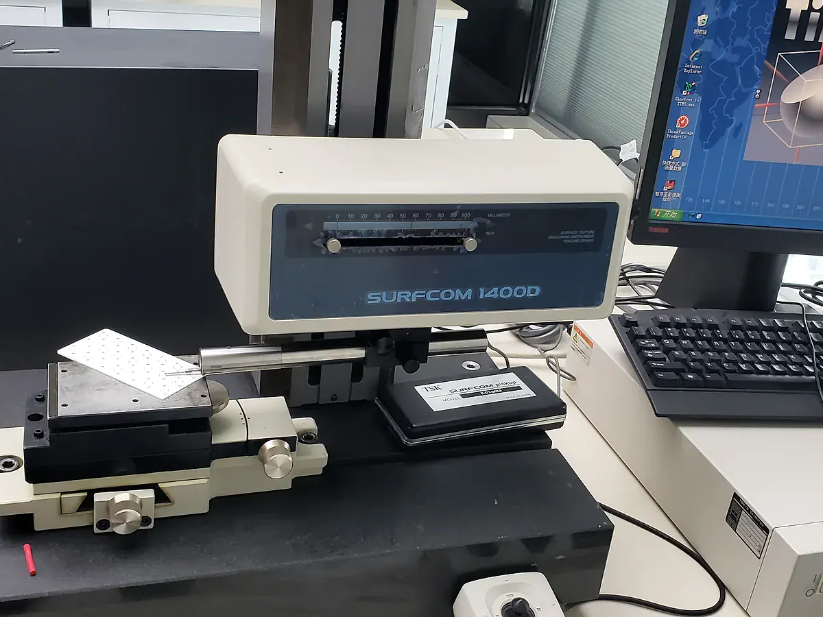
The result can be checked through fired profilometry or cross-section and electrical coupons. Where possible, keep readings before and after the next thermal or mechanical operation; the delta often reveals more than the final value.
The failure pattern to investigate is accepting a wet thickness while the functional fired layer is out of range. Before changing materials, confirm orientation, lot history, measurement method and acceptance limits.
Measure Location and Topography
The physical starting point is straightforward: Average thickness can hide thin edges, mesh marks and step coverage. From there, local minimums often govern current density or dielectric breakdown. For thick film fired thickness, the important issue is the amount of process margin left after normal variation is included.
On the drawing and in the review record, define measurement locations and profile features. Keep the requirement functional wherever possible, while making any safety- or interface-critical boundary unambiguous.
A production trial should capture maps or cross-sections at critical transitions. Record the condition of the specimen and the next operation so that a later change can be traced to a specific stage.
If the team sees good centre readings with edge failures in service, pause before adding inspection or rework. First check whether the layout and the qualified process window are asking for contradictory outcomes.
A Worked Engineering Review
A conductor shows higher path resistance even though the wet print looks normal. Compare deposit mass and wet thickness to prior lots, then measure dried and fired thickness at the same locations. If wet deposit is stable but fired thickness is lower, review burnout and peak-zone records as well as paste solids condition. If centre thickness is normal but edge profile is thin, investigate release and screen aperture. Electrical sheet resistance together with profile data separates material resistivity from insufficient cross-section.
Design Review Checklist
- Define wet, dried and fired measurements separately.
- Control drying load and airflow.
- Provide burnout time for deposit mass.
- Map fired thickness at functional locations.
- Correlate thickness with electrical performance.
Questions Engineers Commonly Ask
What is the correct shrinkage percentage?
There is no universal value. It depends on formulation, deposit and process. Establish it experimentally for the qualified paste and construction.
Can deposit weight replace thickness?
Weight is useful for consistency but does not reveal local profile or edge thinning. Use both where geometry matters.
Why can fired thickness vary across one substrate?
Screen, support, blade, aperture density, release and furnace loading can create positional differences.
Related Engineering Resources
Closing Note
Thickness control is a chain of transformations. Measure the stage that answers the current question, then connect the final fired profile to the electrical or insulation function.