
On this page
A flexible printed heater can have the correct pitch and still mate incorrectly with its connector. Contact pressure, insertion travel and locking depend on the finished tail construction, not only the base film. The connector review must show which conductive face enters the contact system, how far it travels, and which complete laminate thickness the connector is designed to retain.
System boundary
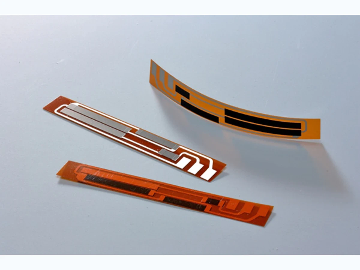
A polymer-supported printed heater with a connector-compatible reinforced tail, its mating FPC/FFC connector, receiving board, routing space and power circuit. A printed tail is not automatically interchangeable with a copper FPC or flat cable of equal pitch.
Integration interfaces
| Interface | Required input | Thick film role | Validation owner |
|---|---|---|---|
| Finished tail to connector contact cavity | Total thickness, width, pitch, contact finish and conductor-facing direction. | The heater termination must present a mechanically and electrically compatible contact surface. | Heater and connector engineers review the actual mating construction. |
| Tail edge to insertion and locking features | Insertion datum, exposed contact length, reinforcement extent and latch engagement. | The termination region needs repeatable positioning without loading the active printed area. | Mechanical integrator verifies fit and assembly access. |
| Mated connector to heater-current path | Operating current, contact temperature, circuit arrangement and environmental conditions. | Heater current passes through a localized contact interface that requires its own qualification. | Electrical integrator validates connector use within its applicable specification. |
Integration risks
| Risk | Control or verification | Validation owner |
|---|---|---|
| Base-film thickness is mistaken for finished mating thickness. | Measure and specify the complete local stack including reinforcement and bonding layers. | Tail supplier and incoming quality owner. |
| The actuator closes on a partly inserted tail. | Use a validated insertion witness and the connector-specific operating procedure. | Assembly engineer. |
| A mechanically fitting printed termination has unsuitable contact behavior. | Verify material/finish compatibility and loaded electrical performance separately. | Electrical and materials owners. |
System integration decisions
- Use the exact connector mating drawing and finished tail stack.
- Separate conductive contact length, reinforcement length and insertion depth.
- Verify full insertion and retention before applying heater current.
Start with the complete connector part number
Pitch alone does not define an FPC/FFC interface. Connector variants can differ in contact side, accepted cable thickness, insertion direction, retention features and actuator operation. Obtain the controlled mating drawing for the exact part mounted on the receiving board.
Identify whether the device uses a movable actuator, a one-action lock or another mechanism. Instructions for a back-flip connector cannot be applied universally to every visually similar housing. The assembly instruction should name the variant and show the required initial and final states rather than using an ambiguous instruction to push the cable into the slot.
Dimension the stack that actually enters the cavity
Create a local section through the mating tongue. Include the polymer carrier, conductor, any cover layer present in the cavity, adhesive and reinforcement. Distinguish the stiffener's own thickness from total finished thickness. A dimension on the original film roll does not describe the reinforced tail.
For an illustrative stack, 0.10 mm of tail construction, 0.15 mm reinforcement and 0.03 mm bonding layer sum to 0.28 mm before considering their tolerances and actual processed state. Whether that fits is determined by the chosen connector's mating requirement, not by rounding the result to a familiar nominal thickness. These values are an arithmetic example, not a recommended heater laminate.
Keep conductive exposure separate from reinforcement
Mark the leading edge, contact exposure, cover-layer edge and reinforcement endpoint on the same drawing. The connector contacts must land on the intended termination surface when the tail is fully inserted. A stiffener can support the tongue without being the surface that makes electrical contact.
Review tolerance in cutting and layer registration as well as nominal lengths. If the cover layer advances into the contact zone, full insertion can still place a contact on insulation. If exposed conductors extend too far outside the housing, the surrounding equipment must preserve their required electrical separation. Do not solve an insertion problem by casually extending exposed print.
Show the conductive face from the assembler's viewpoint
Top-contact and bottom-contact descriptions depend on the connector drawing's orientation. Translate that orientation into an assembly view with the actual board, cable approach and visible tail face. A photograph of the opposite side of the equipment can reverse an otherwise correct instruction.
Where identification is necessary, use an approved feature on an inactive handling region or the equipment fixture. It must not contaminate contact pads or change mating thickness. Confirm that the identification remains visible at the stage where the assembler chooses orientation; a mark hidden inside the connector cannot prevent reversed insertion.
Define how full insertion will be observed
Use the specified tail edge or another controlled datum to establish insertion travel. A printed witness line can be helpful only if its location is controlled relative to the mating geometry and its appearance after insertion is unambiguous. A random edge of reinforcement is not automatically an insertion gauge.
Check left and right sides for skew. One corner can reach the stop while the other remains short, particularly when access forces the tail to approach at an angle. The receiving enclosure must provide the straight insertion and actuator-access space required by the connector. An assembly that works only before the board is installed may need a different documented installation sequence.
Review fit through independent observations
Do not combine all checks into a single continuity result. A partially mated tail may conduct at low test current but have unstable contact or inadequate retention during operation.
| Interface feature | Required evidence | What a continuity check cannot prove |
|---|---|---|
| Finished mating thickness | Measured stack within the exact mating specification | Correct contact pressure or actuator loading |
| Conductive face | Orientation matched to the connector contact side | Absence of unintended alternate conductive paths |
| Contact exposure | Pad window aligned with full-insertion contact location | Sufficient contact overlap after routing |
| Insertion depth | Both sides reach the defined final position | Stable retention of a skewed tongue |
| Lock state | Connector-specific final locking position confirmed | Undamaged lock and proper mechanical capture |
| Loaded connection | Qualified current and temperature observations | Performance inferred from a small test current |
Prevent the installed route from extracting the tail
After mating, route the free tail without transferring assembly pull or twist directly into the contact region. The reinforcement transition can become a lever against the housing if the nearby cable route is forced into place. Provide the required free geometry and equipment-side support while preserving the connector's service access.
The routing review does not replace the separate bend qualification of the printed laminate. Its purpose here is to confirm that the accepted insertion state survives the rest of assembly. Reinspect the witness position and electrical connection after enclosure closure or cable restraint, not only immediately after the operator closes the actuator.
Qualify the actual termination material and service sequence
Mechanical compatibility does not establish that a printed silver or other termination finish is appropriate for the selected contact system. Review surface material, thickness, roughness, protective treatment and expected mating history with the responsible suppliers. Do not transfer a copper-FPC connector rating to an unreviewed printed termination.
Use representative completed tails and mounted connectors for the approved electrical and mechanical verification. Include the intended removal and remating sequence if service requires it, with inspection for pad damage, reinforcement separation or actuator damage. Record which interface changed when an intermittent connection appears. The released drawing should preserve the complete stack, contact orientation, insertion datum and compatible connector identity together.
Review the printed-heater tail interface
Send the finished tail construction and the exact connector specification so fit and electrical compatibility can be reviewed together.
- Connector full part number, mating drawing and operating instructions.
- Tail cross section with finished thickness tolerances, materials and reinforcement boundaries.
- Contact-face orientation, exposed pad geometry and full-insertion datum.
- Heater current conditions, installed routing, service sequence and available mating observations.
The drawing-upload form loads as you reach this section.