
On this page
Reducing heater resistance increases power only while the source maintains the assumed voltage. Once a continuous current limit controls the output, a lower resistance can instead reduce delivered power. A load-line review locates the actual operating point and crossover, preventing a slow-start correction from making the heater receive even less energy.
System boundary
A drawing-defined resistive thick-film heater, its harness, switching stage and DC source with specified continuous constant-voltage/constant-current behavior. Hiccup, foldback, shutdown and constant-power source modes require their own characteristic.
Integration interfaces
| Interface | Required input | Thick film role | Validation owner |
|---|---|---|---|
| Heater resistance to source characteristic | Cold and operating resistance, voltage setting, continuous current limit and source behavior. | The printed heater defines a load line that intersects the available source envelope. | Power and heater engineers verify the applicable operating region. |
| Harness to regulated observation boundary | Lead resistance, switching drops and local or remote sensing location. | Heater-terminal power can differ from the power delivered to the complete series circuit. | Electrical integrator verifies the actual voltage boundary. |
| Delivered power to startup requirement | Initial thermal state, load energy demand, losses and required completion condition. | Available electrical power must be assessed before attributing slow heating to the pattern. | Thermal and controls owners validate the installed start. |
Integration risks
| Risk | Control or verification | Validation owner |
|---|---|---|
| A lower-resistance redesign receives less power in the current-limited region. | Compare candidates on the piecewise source-load envelope. | Electrical design owner. |
| A current limit is assumed while the source actually shuts down or retries. | Use the exact documented and observed source mode. | Power-system integrator. |
| Nominal source voltage is assigned to the heater despite significant series loss. | Measure voltage at the specified heater boundary and retain the harness model. | Validation engineer. |
System integration decisions
- Confirm whether the actual source supports continuous current limiting.
- Calculate the CV–CC crossover using the complete load boundary.
- Evaluate proposed resistance changes on the correct side of that crossover.
Confirm the source characteristic before using the model
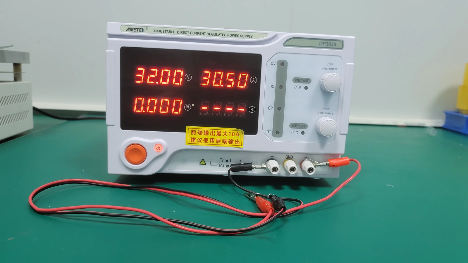
A continuous CV/CC source regulates voltage while the required load current remains below its current setting. When that current would exceed the setting, it reduces voltage and regulates current instead. An overload shutdown, timed retry or foldback characteristic is not represented by this simple rectangular operating envelope.
Read the selected source's behavior and confirm it with appropriately rated instrumentation under the approved test plan. A front-panel current setting can refer to different functions on different equipment. The model is useful only after the actual source mode, sensing location and other active limits are known.
Locate the resistance at the crossover
For an ideal source set to voltage Vs with continuous current limit Ilim, the crossover resistance is Rx = Vs/Ilim. A resistive load above Rx can operate at the voltage setting while drawing less than the current limit. A load below Rx requires more current than allowed at that voltage, so the source reduces its output voltage.
This is a load-line intersection, not a heater material property. Changing either source setting moves Rx even if the printed circuit is unchanged. If the source regulates at its own terminals, use the total series resistance presented there; heater-only resistance is insufficient when harness or switching resistance materially contributes.
Calculate power on both sides of the crossover
In the current-limited region, load power is Ilim²R and rises with resistance. In the voltage-regulated region it is Vs²/R and falls with resistance. Under this idealized model, total load power reaches VsIlim at Rx. The peak is an electrical availability result, not a recommendation to operate a heater at maximum source power.
For a hypothetical 24 V source with a 3 A continuous limit and negligible series loss, Rx is 8 Ω. A 4 Ω heater receives 12 V and 36 W, not 144 W. At 8 Ω it receives 24 V and 72 W. At 12 Ω it receives 24 V and 48 W. A resistance change therefore needs its operating region stated before it can be described as a power increase.
P(R) = Ilim²R for R ≤ Vs/Ilim; P(R) = Vs²/R for R ≥ Vs/Ilim
- Vs is the regulated voltage setting; Ilim is the supported continuous current limit.
- R is the resistive load at the source's defined regulation boundary; P is power entering that load.
Ideal steady CV/CC source without an additional power ceiling, foldback, transient limitation or appreciable reactive load.
Use the envelope to evaluate a resistance change
The following calculations use the same hypothetical source. They demonstrate why a lower cold resistance is not a universal cure for slow warm-up.
| Resistance change | Operating region | Power before → after | Interpretation |
|---|---|---|---|
| 4 Ω → 2 Ω | Both current limited | 36 W → 18 W | Lower resistance reduces available input |
| 4 Ω → 6 Ω | Both current limited | 36 W → 54 W | Higher resistance increases available input |
| 12 Ω → 8 Ω | Voltage region to crossover | 48 W → 72 W | Lower resistance increases input in this range |
| 8 Ω → 12 Ω | Crossover to voltage region | 72 W → 48 W | Higher resistance reduces input |
Follow the measured resistance trajectory through startup
Use the finished heater's resistance-temperature behavior rather than assuming every thick-film material has the same sign or magnitude of change. A trajectory that crosses Rx changes which power relationship governs the next part of warm-up. Local temperatures can also make the total resistance a less direct indicator of the hottest printed region.
Do not infer that reaching the crossover guarantees continued heating to the target. The thermal system can reach a balance between input and losses before the desired condition. Combine the available-power curve with the relevant installed heat-loss and stored-energy model, preserving their separate assumptions.
Separate the heater from the complete source load
With local source sensing and a series harness resistance Rs, the crossover involves R_heater + Rs. In the current-limited region, heater power remains I²R_heater while I²Rs is dissipated elsewhere. At the crossover, the source's maximum total load power is not all useful heater input.
Remote sensing can change the regulated boundary but cannot remove current, voltage-compliance or thermal limits in the wiring. Use the source's specified arrangement and evaluate the actual terminal observations. Raising voltage to compensate an unexplained loss is not a substitute for inspecting a deteriorating connection or reviewing the harness temperature.
Measure the transition instead of trusting nominal settings
Record source voltage, heater-terminal voltage, current, limiting-state indication and relevant temperatures from the defined initial state. A slow display may miss a brief transition or another source limit. Use synchronized measurements that resolve the event of interest without exposing personnel to unqualified live connections.
Compare observed operating points with the proposed envelope. A substantial discrepancy can indicate another active power ceiling, wiring drop, supply dynamics or a nonresistive load component. If repeated shutdowns occur, use the startup-retry diagnostic rather than forcing those intervals onto the continuous CC curve.
Review the source and heater as one startup interface
A proposed correction may involve heater resistance, source capability or a permitted startup sequence. Evaluate its effect on both cold-start power and later operation. More delivered startup power can also increase local temperature or connection stress, so a faster start is not sufficient acceptance evidence.
Retain the selected source characteristic, resistance range, harness boundary and measured trajectory with the heater drawing. The completed review should explain which regime controls startup and why the chosen change helps there. Keep protective thresholds and equipment limits under their responsible owners rather than adjusting them until one specimen happens to warm successfully.
Review the heater startup load line
Send the actual source envelope and finished resistance range before changing the printed heater to address slow startup.
- Source model, voltage/current settings, operating modes and additional power limits.
- Heater cold resistance range and applicable resistance-temperature measurements.
- Harness and switch resistance, sensing boundary and synchronized startup traces.
- Initial thermal load, required startup outcome and independently defined protective limits.
The drawing-upload form loads as you reach this section.