
On this page
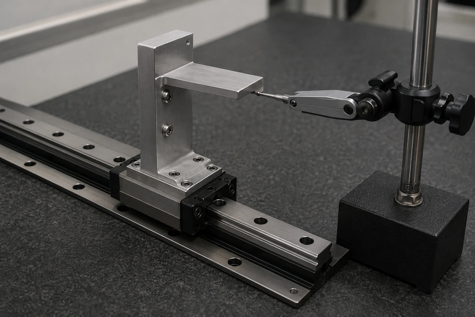
A linear resistor track can report its contact position consistently while a tool, valve connection or other working point on the same carriage occupies a different longitudinal position. The difference becomes important when the sensing line is offset from that working point and the guide allows a small rotation. Resolving the electrical signal more finely does not remove this mechanical lever arm. The installation review must identify which point the application needs to know and which point the sensor actually observes.
System boundary
A resistive linear-position element, its contact carrier, a nominally rigid moving carriage, the guide and a defined working point. The analysis addresses small rotational installation errors. Electrical loading, track wear, digital filtering and machine protective functions have separate owners.
System integration decisions
- Put the working point, contact carrier and sensing line in one signed coordinate drawing.
- Allocate angular motion through the transverse offsets before spending the full error budget on resistor linearity.
- Validate the working-point relationship under the installed loading and direction states, not only the unloaded sensor transfer.
Define position at a physical point, not at the sensor label
Start with the point whose displacement matters to the application. It might be an actuator attachment, the contact face of a positioning fixture or a carriage datum used by another assembly. State the direction in which position is required. A sensor mounted elsewhere on the moving system does not automatically measure that point, even if both parts are described as moving along the same axis.
Metrology distinguishes this offset-related error from the intrinsic scale or sensor error: angular motion can turn distance between the sensing line and the point of interest into a longitudinal difference. The same geometric concern applies when a resistive contact observes motion instead of an optical scale. This does not transfer an encoder manufacturer's precision rating or installation capability to a printed resistor card.
Draw the transverse lever arms and the permitted rotations
Choose x along the required travel, y transverse to it in one direction and z in the remaining perpendicular direction. Mark the vector from the sensing point to the working point. Its transverse components are delta-y and delta-z. Mark positive rotations using the same right-handed convention. The drawing must show the sensing contact or its mechanically equivalent attachment, not merely the outside edge of the resistor substrate.
For a small rotation common to both points on a rigid carriage, the change in their relative x position is approximately delta-z times the rotation about y, minus delta-y times the rotation about z. A vertical offset therefore couples to pitch about y, while a lateral offset couples to yaw about z in this convention. Rotation about x does not produce a first-order x difference through this expression; it can still change contact conditions or introduce other assembly errors.
delta-e_x ≈ delta-z × delta-theta_y − delta-y × delta-theta_z
- delta-y and delta-z are signed transverse components from the sensing point to the working point.
- delta-theta_y and delta-theta_z are changes in small carriage rotations from the chosen reference state, in radians.
- delta-e_x is the resulting change in working-point position relative to the sensor-derived position along x.
Both points belong to the same effectively rigid body; offsets remain constant; rotations are small; the coordinate convention is shared. Relative flexure and changing contact geometry require additional terms.
Convert guide-angle change into the same units as the position budget
Consider an illustrative assembly with a 40-millimeter vertical offset and a pitch change of 0.2 milliradian from its reference state. The first-order position difference is 0.008 millimeter, or 8 micrometers. This is a geometry example, not a proposed tolerance or sensor performance. If a separate lateral offset exists, its yaw contribution must also be evaluated with the correct sign.
A design can reduce this contribution by reducing the relevant lever arm, reducing angular change or measuring the working point more directly. Changing converter bit count does none of these. An offset can be small in one mounting view but substantial in the other, so a side elevation alone is insufficient. Keep the pitch and yaw allocations separate until their bounds and correlation are known; coincidental cancellation at one position is not a reliable error-control strategy.
| Quantity | Required definition | What it prevents |
|---|---|---|
| Working point | Named point and x-direction in the assembly coordinate frame | A sensor-location measurement being mistaken for application position |
| Transverse offsets | Signed delta-y and delta-z from sensing point to working point | Missing one rotation-sensitive lever arm |
| Angular change | Pitch and yaw relative to the calibration state, by position and load | Using an absolute mounting angle as though it were the entire motion error |
| Relative carrier motion | Deflection or play between contact attachment and carriage | Applying a rigid-body model to a flexible linkage |
| Reference observation line | Actual position of the independent measurement axis | Reproducing the same offset error in the validation reference |
Keep offset error separate from travel-axis misalignment
A sensing axis tilted relative to a straight travel direction introduces a projection relationship even if the carriage never changes its angle. That is a different geometric condition from a transverse offset combined with changing carriage rotation. In the small-angle limit, a simple cosine projection changes with the square of the angle, while the offset term above is first order in rotation. Which one matters depends on the actual mounting geometry.
Do not add an arbitrary sine or tangent correction without defining the two lengths and points being compared. Different geometric constructions can produce those functions. Use the stated small-rotation rigid-body relation only within its assumptions, or use the actual coordinate transformation when larger rotations or changing offsets matter. A correction equation belongs to a specific measurement geometry, not to the word linear on the product description.
Identify when the angular state changes
Guide pitch and yaw can vary along travel and with applied moments. Cable forces, an offset actuator load or a change in fixture loading can alter the angular state even at the same nominal x coordinate. Record the load application point and orientation, not only the total force. A force acting close to the guide support and the same force acting through a longer lever arm need not produce the same rotation.
Direction-dependent results require careful interpretation. A forward/reverse electrical difference might arise from the contact system, mechanical play, signal delay or guide attitude. Comparing the working point with the sensing attachment under settled conditions can help locate the contribution. It does not by itself prove which guide element is defective. Keep raw position, load state and direction records before using a single hysteresis number to describe several mechanisms.
Use a reference that observes the required relationship
A validation reference placed beside the resistor track can confirm the track's installed transfer while missing error at a distant working point. Conversely, a reference observing the working point measures the combined result but does not automatically separate electrical and geometric contributions. Decide whether the experiment needs the total working-point error, a mechanical attribution or both.
For attribution, the metrology plan can include independent observations of relevant position or angle states, with uncertainty adequate to resolve the allocated effect. Specify the physical observation points and coordinate transformation before collecting data. An instrument display with finer digits is not sufficient if its mounting repeats the same unwanted lever arm. The qualified metrology owner chooses equipment and safe access; no particular reference instrument or achievable uncertainty is implied.
Decide what a position-only correction can represent
If angular motion is stable and repeatable as a function of x under one mechanical state, a system correction may absorb part of its effect. That correction then describes the installed assembly under the state used to establish it. It is not an improved intrinsic linearity specification for the loose resistor card. Keep the uncorrected transfer available so the source of improvement remains visible.
A correction depending only on x cannot distinguish two different guide angles occurring at the same x under different loads. Adding more calibration points along travel does not supply that missing state information. The system owner must either bound the state dependence, change the mechanical arrangement or use an appropriate additional observation. Avoid extrapolating a correction to changed load moments, rebuilt guides or relocated sensing brackets without rechecking the relationship.
Carry the geometry into the released interface drawing
The useful output of this review is a drawing and validation record connecting the resistor contact position to the specified working point. Include the coordinate convention, attachment, relevant offsets, allowed mechanical states and the basis of any installed correction. Specify which dimensions belong to the card and which belong to the guide, carrier or complete assembly; otherwise an installed positioning problem can be incorrectly assigned to the printed pattern.
Revisit the relationship when a bracket, contact carrier, cable route or working-point location changes. A card with identical artwork can participate in a different lever arm after such a modification. Quotation and prototype review are more effective when the application drawing accompanies the electrical curve requirement. The supplier can then review the track interface while the mechanical and metrology teams retain responsibility for the working-point accuracy demonstrated by the assembly.
Provide the sensing-line and working-point geometry
Send the installed coordinate drawing alongside the linear-track electrical requirement so geometric and electrical error allocations remain separate.
- Working point, travel direction, sensing contact location and signed transverse offsets.
- Guide pitch and yaw information across relevant position, load and direction states.
- Contact-carrier attachment, relative-motion allowance and load application points.
- Independent reference observation line, uncertainty allocation and any installed correction state.
The drawing-upload form loads as you reach this section.