
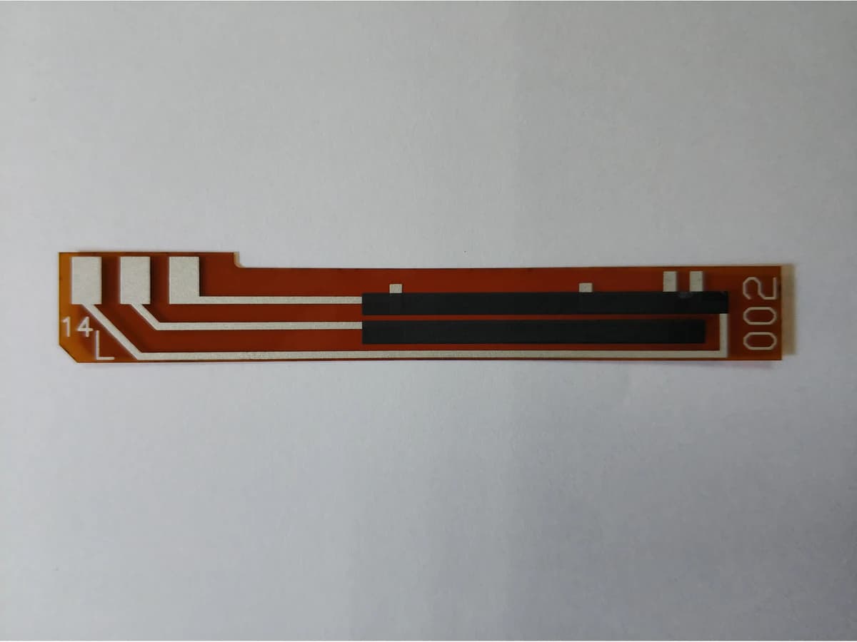
Overview
A linear printed position track converts mechanical travel into an electrical transfer only when the resistive element, collector, wiper, terminals, substrate, housing, electronics, calibration, and environment operate together. A geometrically straight carbon or thick-film path does not automatically create a linear sensor output. Source and load impedance alter the divider transfer; conductor overlaps and inactive end regions affect usable travel; printing and cure or firing change the effective width and sheet resistance; the wiper creates pressure, contact resistance, wear, debris, bounce, and local current density; and housing tolerances shift the relationship between physical position and electrical position. Flexible polymer and fired ceramic routes require different material and process evidence and must not be blended. This guide defines a system-level transfer model, error allocation, track design workflow, and validation matrix without claiming any ThickFilmPCB linearity, resolution, cycle life, resistance range, travel, material, contact system, or environmental rating. The real drawing, wiper assembly, electronics, named material stack, process records, and measured production-intent samples control the answer.
Engineering review matrix
Each row links a design variable to evidence that can support a drawing or release decision.
| Variable | Control question | Verification route |
|---|---|---|
| Travel and datum definition | Specify physical zero, electrical start, active span, end bands, overtravel, direction, wiper footprint, housing reference, and measurement points. | Use a calibrated position reference and confirm fixture, drawing, software, and report share the same coordinate system. |
| Transfer and error definition | Define unloaded or loaded output, reference line, zero, span, linearity, profile, hysteresis, repeatability, smoothness, calibration, and allowed discontinuity. | Report raw point data and the exact calculation method over the specified active travel and directions. |
| Track material and geometry | Name substrate and resistive system, sheet-resistance convention, width, length, thickness, print direction, taper, corners, overlaps, collector, and trim features. | Measure production-intent coupons and correlate actual geometry, thickness, resistance, and transfer by position. |
| Wiper contact system | Define wiper material, fingers, radius, force, contact area, current, speed, direction, dwell, bounce, lubrication rule, debris, and wear path. | Log dynamic contact output and resistance, inspect wiper and track, and compare staged wear results. |
| Electronics loading | Set excitation, source impedance, input impedance, leakage, filter, protection, sampling, ADC behavior, connector and cable resistance, and diagnostic currents. | Measure the complete sensor-electronics transfer and repeat with bounded load, supply, leakage, and fault conditions. |
| Mechanical tolerance and support | Allocate housing, actuator, stops, carrier, substrate, mounting, flatness, alignment, preload, flex, vibration, and thermal-expansion tolerances. | Measure assembled units at tolerance conditions and correlate electrical position to an external calibrated reference. |
| Thermal and environmental exposure | Specify operating and storage profiles, gradients, humidity, condensation, fluids, cleaners, particles, sulfur or corrosives, UV, and sealing. | Condition production-intent assemblies and compare transfer, contact, insulation, adhesion, wear, and visual baselines with recovery stated. |
| Calibration and change control | Define factory and system calibration points, coefficients, software version, residual limits, traceability, recalibration, material changes, and acceptance records. | Retain raw measurements, applied corrections, residual error, version links, and requalification triggers. |
Controlled model
Loaded transfer, linearity, and contact-error model
Define physical and electrical datums before measuring error. Start with an ideal divider, add finite load, end resistance, wiper contact, track-profile variation, mechanical offset, temperature, and calibration terms, then validate direction, speed, load, environment, and wear.
u = (x − x₀)/L_activeNormalizes physical wiper position to the defined active travel between electrical datums.
- Units
- u dimensionless; x, x₀, and L_active in the same length unit
- Use boundary
- Requires an explicit mechanical datum, electrical start, active travel, overtravel, and direction. Housing compliance, backlash, and wiper footprint can make contact position differ from commanded position.
K_ideal(u) = V_out/V_exc = uIdeal unloaded transfer for a uniform end-to-end resistive track with negligible contact and terminal effects.
- Units
- K and u dimensionless; voltages in V
- Use boundary
- Not valid with taper, finite load, source resistance, collector resistance, end effects, contact resistance, leakage, or nonuniform sheet resistance.
R_lower = uR_T; R_upper = (1−u)R_T; K_L = (R_lower ∥ R_L)/[R_upper + (R_lower ∥ R_L)]Shows the position-dependent nonlinearity introduced by finite electronic load across the lower segment.
- Units
- Resistances in Ω; K_L dimensionless
- Use boundary
- A simplified divider with constant total resistance and no source, collector, wiper, leakage, or frequency effects. Use the real circuit for final analysis.
e_lin(u) = K_meas(u) − K_ref(u)Pointwise linearity or profile deviation from the agreed reference line or calibrated law.
- Units
- Dimensionless, often reported as % of specified electrical span
- Use boundary
- The result depends on reference-line definition, endpoint treatment, direction, sampling, filtering, excitation, load, speed, temperature, fixture, and included end zones.
P_local ≈ I²R_segmentScreening relation for electrical heating in a track segment or contact region.
- Units
- P in W; I in A; R_segment in Ω
- Use boundary
- Does not predict local temperature or allowable current. Current crowding, wiper footprint, pulse, substrate heat path, and contact films need specific analysis and tests.
Decision comparison
| Decision | Route A | Route B | Verification |
|---|---|---|---|
| Independent linearity versus end-point calibration | Independent linearity compares output with a best-fit or otherwise defined reference and can separate shape from overall zero and span. | End-point calibration forces the transfer through defined endpoints and may absorb zero and span while leaving intermediate profile error. | State the reference-line method, active travel, endpoints, direction, filtering, and calibration in the drawing and report; do not compare values from different definitions. |
| Rigid ceramic versus flexible polymer track | A ceramic route can support fired functional layers but requires brittle-part mounting, fired material compatibility, and assembly stress control. | A polymer-film or organic-board route uses lower-temperature printed materials and adds flex, thermoforming, solvent, dimensional, adhesive, connector, and handling boundaries. | Qualify each stack separately with its production process and housing; do not transfer a paste, firing or cure, wear, or environmental result between them. |
| Static transfer accuracy versus dynamic contact quality | Slow point measurements characterize gross transfer, zero, span, profile, repeatability, and hysteresis under one fixture state. | Motion introduces speed, direction, vibration, bounce, contact force variation, debris, bandwidth, sampling, filtering, and electrical noise. | Measure time-resolved output and contact behavior during representative motion in addition to static position points. |
- Use one coordinate system and direction convention in mechanical drawing, artwork, fixture, test software, data, and calibration table.
- Report dead bands, end regions, overtravel, discontinuities, open-circuit behavior, and filtering explicitly rather than hiding them inside one linearity number.
Linear track design and validation workflow
The order makes assumptions and ownership visible before a result is promoted to a requirement.
- 01
Define mechanical-to-electrical mapping
Set mechanical and electrical datums, direction, active travel, end margins, overtravel, wiper footprint, output law, reference-line definition, zero, span, linearity, hysteresis, repeatability, resolution or smoothness, and failure behavior.
- 02
Model the complete circuit
Include excitation tolerance, source resistance, total and segment resistance, collector and terminal paths, wiper contact, electronics load, leakage, protection, filter, ADC sampling, calibration, open wiper, and short conditions. Calculate position-dependent loading rather than one endpoint.
- 03
Choose one material route
Select ceramic fired thick film or a defined polymer system according to substrate, assembly, environment, geometry, contact, and process constraints. Name every conductor, resistor, dielectric, coating, adhesive, terminal, and wiper material; keep routes separately qualified.
- 04
Design track and interfaces
Set effective width and length, sheet-resistance family, print direction, end overlaps, collector, wiper transition, terminal location, current path, corners, inactive margins, trim or profile correction, protection keep-outs, registration, and inspection datums.
- 05
Integrate wiper and housing
Define contact material, shape, number of fingers, force, alignment, velocity, acceleration, vibration, travel stops, carrier stiffness, debris management, sealing, connector, mounting, substrate support, and tolerance stack from external shaft or actuator to contact path.
- 06
Measure static and dynamic performance
Test loaded output at position points in both directions and at relevant speeds, excitation, loads, temperatures, mounting states, and filtering. Record raw and calibrated transfer, hysteresis, repeatability, contact interruptions, noise, resistance, and uncertainty.
- 07
Validate use and wear
Apply representative motion cycles, dwell, electrical load, vibration, shock, humidity, contamination, chemicals, temperature, assembly, storage, and fault cases. Inspect wear, debris, wiper and track condition, terminals, adhesion, and output drift before release.
Failure controls
These are review prompts, not evidence that every risk applies or that every test is available.
- A
Calling a straight printed track linear without defining reference line, active travel, loading, end regions, direction, fixture, and calibration
- B
Ignoring finite electronics input impedance and creating position-dependent divider curvature that calibration does not robustly remove
- C
Using static points to release a moving contact while bounce, speed, vibration, debris, wear, force, and filtering remain untested
- D
Mixing fired ceramic and polymer printed-material evidence or transferring a cure, paste, wear, flexibility, or environment assumption between routes
- E
Allowing housing and wiper tolerances to shift electrical position even when the printed track meets artwork dimensions
- F
Publishing a cycle-life, linearity, resolution, temperature, resistance, or chemical rating without production-intent system evidence
Reference boundary
Public method sources
These sources support the engineering method and terminology used in this technical guide. They do not establish a ThickFilmPCB material list, capability limit, customer result, certification, or finished-product specification.
- 01TE Connectivity — Rotary and Linear Potentiometer Position Sensors
Supports the basic potentiometric relationship among excitation, moving contact, output, travel, linearity, and mechanical sensor construction; TE product specifications do not establish printed-track or ThickFilmPCB performance.
- 02DuPont 7105 Carbon Conductive Composition
Supports formulation-specific carbon printing, cure, thickness, sheet-resistance, flex, abrasion, and substrate boundaries for one named polyester test system; it does not qualify a wiper sensor or another substrate.
- 03NIST Technical Note 1297 — Measurement uncertainty
Supports identifying and propagating measurement-uncertainty components in position and electrical transfer measurements; it supplies no sensor tolerance or acceptance value.
Inputs for a practical review
Unknown values may be labelled unknown. The review should convert uncertainty into an explicit decision or validation task.
Send Drawings- 01
Mechanical drawing with datums, direction, stroke, active travel, end bands, overtravel, wiper path and footprint, stops, alignment, mounting, and tolerance stack
- 02
Electrical schematic with excitation, source and load impedances, target resistance, transfer law, collector, wiper current, filter, ADC, protection, calibration, and diagnostics
- 03
Required zero, span, linearity or profile definition, hysteresis, repeatability, smoothness or noise, discontinuity, response, and failure behavior
- 04
Substrate, resistor and conductor systems, cure or firing route, thickness, track and terminal geometry, coating, adhesive, connector, and prohibited substitutions
- 05
Wiper material, shape, fingers, force, speed, acceleration, dwell, direction, cycles, vibration, shock, debris, wear, and contact-current conditions
- 06
Operating and storage temperature, humidity, condensation, fluids, chemicals, cleaning, particles, sealing, UV, and assembly exposures
- 07
Prototype quantity, fixture, sampling grid, dynamic logging, uncertainty, conditioning sequence, acceptance rule, report and traceability requirements