
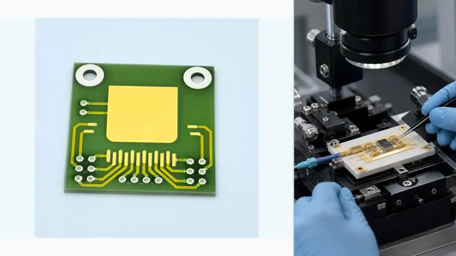
Overview
This application engineering guide maps Optoelectronic and Laser Submount Thermal Interface as a system-level problem. The printed element is reviewed together with mechanics, electronics, heat flow, media exposure, calibration, failure response, and final-assembly validation.
Failure controls
These are review prompts, not evidence that every risk applies or that every test is available.
- A
Overcut, overshoot, taper, or geometry outside tolerance
- B
Recast, debris, carbonization, microcracking, or heat-affected damage
- C
Electrical instability from trim geometry or inadequate post-trim margin
- D
Registration loss between program, datum, artwork, and revision
Engineering review matrix
Each row links a design variable to evidence that can support a drawing or release decision.
| Variable | Control question | Verification route |
|---|---|---|
| Functional objective | For Optoelectronic and Laser Submount Thermal Interface, value adjustment, hole creation, separation, or marking use different beam, geometry, and acceptance logic. | Release the operation only against a named drawing feature or measured target. |
| Energy interaction | Wavelength, pulse, energy, focus, speed, repetition, assist, and material absorption control removal and thermal damage. | Establish a process window on representative stacks and monitor critical parameters. |
| Geometry | Kerf, taper, recast, debris, radius, path, trim shape, and distance to conductors or edges influence function. | Inspect the processed feature using its drawing datum and suitable method. |
| Measurement loop | For trimming, probe condition, settling, increments, algorithm, overshoot margin, and final verification form a closed loop. | Record initial, target, final, and stability values with program and lot identity. |
| Post-process integrity | Cleaning, microcracks, heat-affected regions, insulation, strength, and assembly must remain acceptable. | Use visual, dimensional, electrical, and reliability checks selected for actual risk. |
System integration route
The order makes assumptions and ownership visible before a result is promoted to a requirement.
- 01
Define the system transfer function
For Optoelectronic and Laser Submount Thermal Interface, document the functional requirement, operating boundary, interfaces, quantities, and acceptance owner against the current drawing.
- 02
Map mechanical and electrical interfaces
For Optoelectronic and Laser Submount Thermal Interface, control dimensions, datums, layer stack, interfaces, tolerances, and assembly constraints in the released drawing.
- 03
Set environmental boundaries
For Optoelectronic and Laser Submount Thermal Interface, complete set environmental boundaries against the controlled drawing, named assumptions, responsible owner, required evidence, and release decision.
- 04
Build the validation matrix
For Optoelectronic and Laser Submount Thermal Interface, complete build the validation matrix against the controlled drawing, named assumptions, responsible owner, required evidence, and release decision.
- 05
Release assembly-level acceptance
For Optoelectronic and Laser Submount Thermal Interface, close remaining assumptions and link the quoted or released scope to the drawing revision, evidence set, owner, and change-control plan.
Inputs for a practical review
Unknown values may be labelled unknown. The review should convert uncertainty into an explicit decision or validation task.
Send Drawings- 01
Feature or electrical target and drawing datum
- 02
Material stack and laser-access constraints
- 03
Geometry, edge quality, damage, and cleanliness acceptance
- 04
Measurement and program control for closed-loop trimming
- 05
Post-process electrical, mechanical, and reliability checks