
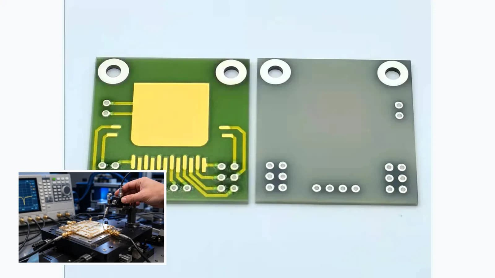
Overview
This application engineering guide maps RF and Microwave Ceramic Circuit Integration as a system-level problem. The printed element is reviewed together with mechanics, electronics, heat flow, media exposure, calibration, failure response, and final-assembly validation.
Failure controls
These are review prompts, not evidence that every risk applies or that every test is available.
- A
Cracking or chipping from machining, handling, mounting, or thermal stress
- B
Registration or bonding loss from surface, flatness, or cleanliness variation
- C
Thermal performance assumed from generic values rather than actual grade and assembly
- D
Metallization adhesion or interface failure after processing and exposure
Engineering review matrix
Each row links a design variable to evidence that can support a drawing or release decision.
| Variable | Control question | Verification route |
|---|---|---|
| Material identity | For RF and Microwave Ceramic Circuit Integration, ceramic chemistry, grade, source data, lot, thickness, surface, and thermal/mechanical properties must match the actual route. | Review source documentation and incoming measurements within stated scope. |
| Mechanical geometry | Outline, thickness, flatness, bow, holes, slots, edge, datum, scribe, and break direction affect printing and assembly. | Measure with a drawing-linked datum and brittle-part method. |
| Surface condition | Roughness, cleanliness, porosity, lapping, polishing, and handling influence print definition, adhesion, deposition, and bonding. | Inspect the controlled surface before metallization or printing. |
| Thermal interface | Conductivity values belong to a named grade and temperature; assembly interfaces and geometry control real heat flow. | Use source data for selection and assembly-level thermal validation for release. |
| Metallization compatibility | Paste, deposited metal, adhesion layer, firing, plating, soldering, and wire bonding need route-specific compatibility. | Qualify the complete material and assembly stack rather than the bare substrate alone. |
System integration route
The order makes assumptions and ownership visible before a result is promoted to a requirement.
- 01
Define the system transfer function
For RF and Microwave Ceramic Circuit Integration, document the functional requirement, operating boundary, interfaces, quantities, and acceptance owner against the current drawing.
- 02
Map mechanical and electrical interfaces
For RF and Microwave Ceramic Circuit Integration, control dimensions, datums, layer stack, interfaces, tolerances, and assembly constraints in the released drawing.
- 03
Set environmental boundaries
For RF and Microwave Ceramic Circuit Integration, complete set environmental boundaries against the controlled drawing, named assumptions, responsible owner, required evidence, and release decision.
- 04
Build the validation matrix
For RF and Microwave Ceramic Circuit Integration, complete build the validation matrix against the controlled drawing, named assumptions, responsible owner, required evidence, and release decision.
- 05
Release assembly-level acceptance
For RF and Microwave Ceramic Circuit Integration, close remaining assumptions and link the quoted or released scope to the drawing revision, evidence set, owner, and change-control plan.
Inputs for a practical review
Unknown values may be labelled unknown. The review should convert uncertainty into an explicit decision or validation task.
Send Drawings- 01
Ceramic family, grade, source document, and lot requirement
- 02
Outline, thickness, flatness, holes, slots, scribe, and edge tolerances
- 03
Surface finish, cleanliness, lapping/polishing, and protected faces
- 04
Metallization/printing, joining, mounting, and heat-path requirements
- 05
Incoming, dimensional, adhesion, thermal, and reliability evidence