
On this page
A plate heater sized for a stationary object does not automatically heat a moving workpiece to the same condition. Transport speed determines how long each material element experiences the heating region, while throughput determines how much energy the heater must supply per second. Those two constraints must be satisfied together before increasing machine speed.
System boundary
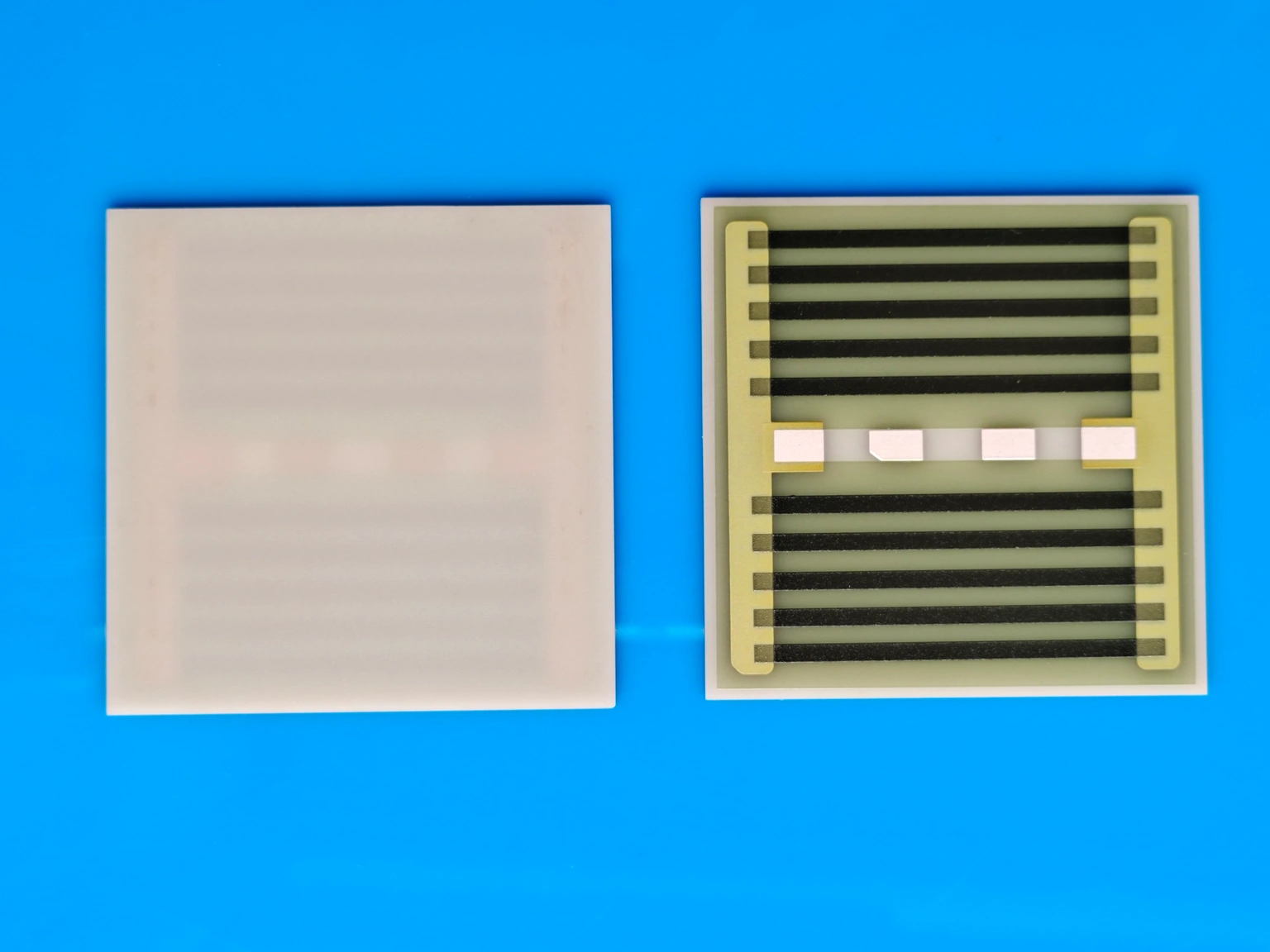
A thick-film heater coupled to a plate or heating surface, moving workpiece or continuous strip, transport mechanism, thermal interface and process sensing. The heater's printed surface is not assumed to be an approved sliding wear surface.
Integration interfaces
| Interface | Required input | Thick film role | Validation owner |
|---|---|---|---|
| Transport motion to thermal exposure | Actual path, speed history, entry/exit locations and effective heating length. | The heater establishes a spatial heat-input region through the reviewed plate interface. | Machine integrator verifies motion and exposure coordinates. |
| Workpiece stream to energy demand | Mass per length or item, feed rate, inlet state and required outlet state. | Electrical heating must supply the workpiece energy and installed losses. | Process and thermal owners establish the throughput budget. |
| Load contact to observed temperature | Contact pressure or gap, surface condition and material-element tracking. | Heat passes through the installed interface rather than directly following the power command. | Validation engineer correlates thermal observations with transported specimens. |
Integration risks
| Risk | Control or verification | Validation owner |
|---|---|---|
| A faster feed halves exposure even though heater temperature is unchanged. | Relate the accepted process condition to actual speed and effective heating length. | Process controls owner. |
| Average power is adequate but heat transfer is too slow for each workpiece. | Evaluate the individual thermal response separately from throughput energy. | Thermal integrator. |
| A transport stop leaves one region over the energized plate. | Define the protected stop and restart sequence for stationary material. | Machine safety and controls owners. |
System integration decisions
- Define effective heating length along the actual workpiece path.
- Check both individual residence time and total material throughput.
- Treat acceleration, gaps and a stopped workpiece as separate operating states.
Measure heating length along the transported material
The relevant length starts where the workpiece meaningfully couples to the heated region and ends where that coupling ceases. It may be shorter than the plate outline because of entry ramps, gaps, edge cooling or incomplete contact. Draw the actual travel line and identify where the process accepts heat transfer.
For a wide strip, the useful region can differ across its width. An edge lifted by a guide or a locally cooler plate margin does not receive the same history as the central line. Preserve lateral position when defining the observation plan rather than treating one centerline measurement as the entire moving load.
Convert transport speed into exposure time
At constant speed v through an effective length L, residence time is L/v. An illustrative 0.15 m heating length gives 5 s at 0.03 m/s and 2.5 s at 0.06 m/s. The unchanged plate geometry therefore provides half the time after the speed doubles.
During acceleration, use the measured position history to find the entry and exit times of a particular material element. Dividing length by the final speed is not correct for an element that traversed the region while speed was changing. Gaps between separate workpieces also matter: they alter heater recovery without extending the exposure of the next part.
t_res = L_effective / v; for variable motion, x(t_exit) − x(t_entry) = L_effective
- L_effective is the active path length in metres; v is transport speed in metres per second.
- t_res is residence time in seconds; x(t) is the tracked material position.
Constant-speed expression applies only over a defined continuously coupled region. Variable motion requires actual entry and exit events.
Check whether the workpiece can respond within that time
Sufficient electrical energy does not guarantee sufficiently fast transfer through the contact. For a screening model with a nearly uniform workpiece temperature and a constant plate temperature, the approach to the plate temperature is exponential, with a time constant determined by participating heat capacity and contact conductance.
If an illustrative time constant is 3 s, a 5 s exposure reaches about 81% of the available plate-to-inlet temperature difference; 2.5 s reaches about 57%. The comparison explains why doubled speed can change the outlet condition despite an unchanged plate sensor. A layered workpiece, changing contact or internal temperature gradient needs a more appropriate model; these percentages are not performance claims.
Calculate energy demand per second of material
For sensible heating, multiply mass throughput by specific heat and the required temperature increase. With a continuous strip, mass throughput equals mass per unit length times speed. Keep latent heat, evaporation or reaction energy separate when those processes occur rather than hiding them inside an unexplained effective heat capacity.
For illustration, a stream of 0.002 kg/s with specific heat 1000 J/(kg·K) and a required rise of 40 K absorbs 80 W. At twice the mass rate it requires 160 W for the same outlet state, before plate losses or heater warm-up. The higher-speed case thus simultaneously asks for more power and less time to transfer that power to each material element.
Define the moving contact without sacrificing the heater stack
Determine whether the workpiece slides on a separate plate, travels across a maintained gap or contacts an approved protective face. A fired thick-film conductor or glass overcoat should not be assumed to withstand sliding abrasion merely because it is hard to the touch. The mechanical interface requires its own wear and contamination assessment.
Record guide loads, pressure distribution and surface condition during motion. A transport tension change can lift an edge or change the contact footprint without changing the nominal speed. Those effects belong in the thermal interpretation. Inspect deposited material or debris that could change coupling, while following the permitted cleaning procedure for the actual surface.
Separate the limiting constraints in the operating map
Build the speed map using both measured outlet condition and the relevant equipment limits. A single successful speed point does not reveal which constraint will fail first when throughput increases.
| Observed limitation | Diagnostic comparison | Likely review direction |
|---|---|---|
| Outlet remains cool with spare heater capacity | Exposure time versus transfer response | Increase effective coupling or review heating length |
| Plate temperature falls during sustained feed | Material energy rate versus available delivered power | Review throughput budget and heater authority |
| Edges differ from the centre | Lateral contact and temperature history | Review widthwise coupling and usable region |
| First items after a gap differ | Plate recovery and entry-state history | Define gap and restart conditions |
| Stopped material continues heating | Stationary exposure with stored plate energy | Implement the approved stop and removal response |
Include deceleration and stopped material in protection
A transport stop changes residence time from a finite passage to an extended stationary exposure. Removing the heater command does not instantly remove stored heat from the plate. The machine owner must define how motion loss, material handling and protective energy interruption interact.
Validate the permitted response under controlled conditions with the relevant safeguards. Do not infer safe stopping from the normal outlet temperature or from the heater's cold resistance. Restart can also expose a fresh region to a plate whose temperature distribution changed during the pause, so identify the material affected by that transition.
Track the same material element through the verification
Synchronize transport position, heater input and temperature observations. A fixed sensor sees successive material elements, while a sensor attached to a workpiece follows one element; these records answer different questions. State which method establishes the required outlet or internal condition.
Retain the entry state, lateral track, speed history and exit assessment for each representative specimen. Review steady feed, the intended speed range and defined interruption events. The resulting specification should tie required throughput to heating length, coupling and accepted material state, allowing a future speed change to be evaluated before the machine is simply commanded to run faster.
Review a moving-load plate heater
Share the transport and material stream together with the heater interface so exposure time and throughput energy can be evaluated independently.
- Plate drawing, effective heating path, contact arrangement and protected working surface.
- Speed and position histories, strip mass per length or item mass and feed rate.
- Material inlet/outlet requirements, thermal properties and any phase-change energy.
- Widthwise observations, interruption states and synchronized material-tracking records.
The drawing-upload form loads as you reach this section.