
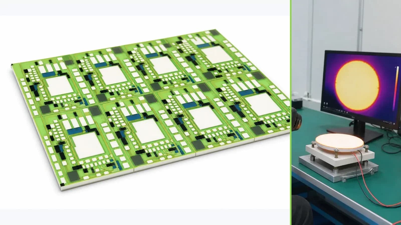
Overview
A ceramic circuit can be one thermal and electrical layer inside a power-module assembly, but the complete temperature path also includes semiconductor junctions, attachment layers, metallization, terminals, baseplates, interface materials, coolers, clamping, enclosure airflow or liquid flow, and the control strategy. This guide organizes those interfaces before anyone assigns a temperature, power, isolation, or lifetime claim to the ceramic alone. It helps a module designer describe heat sources, transient duty, electrical isolation, mechanical restraint, sensing locations, cooling boundaries, and qualification ownership. It does not state that a particular substrate, conductor stack, attachment process, or module construction is available from ChipSimple. Selection and release remain conditional on the drawing, material declarations, supplier data, representative builds, and system-level validation.
Failure controls
These are review prompts, not evidence that every risk applies or that every test is available.
- A
Using a substrate conductivity value as if it were complete junction-to-coolant thermal resistance hides attachments, spreading, interfaces, and boundary conditions.
- B
A small void, warped interface, uneven clamp, or local metallization bottleneck can create a hotspot that a remote surface sensor does not detect promptly.
- C
Power cycling and passive thermal cycling load different interfaces; one cannot be claimed as a substitute without a documented correlation.
- D
Isolation, creepage, and accessible-temperature decisions belong to the full energized assembly and the applicable equipment standard, not to an isolated ceramic photograph.
- E
A model tuned to one sample can conceal lot, assembly, cooler, sensor, and interface-material variation unless validation includes stated tolerances.
- F
Removing raw time-series data, failed specimens, or fixture details makes later thermal and reliability conclusions difficult to reproduce or audit.
Engineering review matrix
Each row links a design variable to evidence that can support a drawing or release decision.
| Variable | Control question | Verification route |
|---|---|---|
| Heat-source map | Which dies or resistive features dissipate heat in every operating and fault state, and how uncertain are the loss estimates? | Correlate electrical loss calculations with synchronized voltage, current, switching, temperature, and cooling measurements on representative hardware. |
| Thermal stack | What materials, thicknesses, areas, surface conditions, attachment layers, void criteria, and contact pressures form each heat-flow path? | Verify the released cross-section and assembly records, then compare measured temperature drops with the model at defined boundary conditions. |
| Cooling boundary | What coolant, flow, inlet temperature, pressure, fouling state, airflow, heat-sink condition, and start-up delay define the cold side? | Control and record boundary conditions during steady and transient tests, including specified degraded-cooling cases. |
| Electrical isolation | Which working and transient voltages, pollution conditions, altitude, coating state, and accessible parts govern insulation coordination? | A qualified safety owner selects applicable standards and validates spacing, dielectric construction, and tests on the complete assembly. |
| Mechanical restraint | How do flatness, clamping pattern, torque, interface-material thickness, vibration, and CTE mismatch load the ceramic and attachments? | Inspect assembly geometry and strain-sensitive locations before and after mechanical and thermal cycling defined by the module owner. |
| Temperature sensing | Where are sensors placed, what do they estimate, and what accuracy, response, calibration, redundancy, and diagnostic behavior are required? | Calibrate the measurement chain, correlate sensor readings to protected locations, and inject permitted open, short, drift, and delay faults. |
| Mission profile | Which steady, pulsed, cyclic, overload, storage, and cooling-loss states determine peak temperature and accumulated damage? | Run the approved profile or a justified acceleration model while retaining cycle definition, raw results, failures, and model correlation. |
Power-module thermal review sequence
The order makes assumptions and ownership visible before a result is promoted to a requirement.
- 01
Draw the complete heat-flow boundary
Start at each semiconductor heat source and trace every parallel and series path to ambient or coolant. Record die attach, conductor and dielectric layers, ceramic, substrate attachment, baseplate, thermal interface material, cooler, fasteners, enclosure, and fluid or airflow. Separate junction temperature, local metallization temperature, ceramic surface temperature, coolant inlet temperature, and ambient temperature because they are not interchangeable measurements.
- 02
Define electrical and mechanical interfaces
Map working voltage, transient voltage, isolation boundary, conductor potential, gate and sensor circuits, creepage route, terminals, wire bonds or other interconnects, and accessible metal. Add clamping force, flatness, fastener pattern, assembly tolerance, vibration, shock, and CTE mismatch. The ceramic selection cannot be reviewed independently of insulation coordination and mechanical restraint.
- 03
Convert mission profile into thermal cases
Provide current, voltage, switching state, loss estimate, pulse duration, repetition, dwell, start-up, overload, regenerative operation, cooling delay, and shutdown behavior. Build steady-state and transient cases rather than one headline wattage. Include manufacturing variation and cooling degradation as explicit sensitivity cases, not hidden margin.
- 04
Place sensors around the decision
Identify what each sensor is intended to protect or estimate, its physical distance from the heat source, attachment, response time, self-heating, calibration, wiring, filtering, and failure mode. A surface sensor can support a correlation model, but it cannot automatically substitute for junction-temperature estimation or prove the hottest local feature.
- 05
Build representative test articles
Use the intended material stack, geometry, attachment, finish, terminals, clamping, interface material, cooler, and control software. Instrument the locations named in the thermal model and retain raw electrical, temperature, flow, pressure, and timing data. Coupon tests may screen materials; the module assembly must address interface and gradient behavior.
- 06
Release with traceable limits
Link the accepted duty envelope to drawing revisions, material lots, assembly instructions, sensor calibration, thermal model revision, test fixture, acceptance criteria, and deviation rules. The OEM or module owner approves system safety and mission-profile suitability; specialized laboratories perform tests that require qualified equipment or controlled high-energy procedures.
Reference boundary
Public method sources
These sources support the engineering method and terminology used in this technical guide. They do not establish a ThickFilmPCB material list, capability limit, customer result, certification, or finished-product specification.
- 01IEC 60747-15:2024 — Isolated Power Semiconductor Devices
Defines requirements for isolated power semiconductor devices and includes switch-level thermal-resistance description. It informs terminology and the module review boundary; it does not qualify a ChipSimple ceramic, module, isolation system, or thermal rating.
- 02IEC 60749-34-1:2025 — Power Cycling Test for Power Modules
Describes a destructive power-cycling method for power semiconductor modules and internal connectors. It supports separating power cycling from generic thermal claims, but the applicable profile, acceleration, and acceptance criteria remain project-owned.
- 03NIST Guide to Secondary Thermometry — Industrial PRTs
Explains comparison calibration, temperature ranges, interpolation, and uncertainty considerations for industrial platinum resistance thermometers. It supports the sensor-chain review only and is not evidence of module performance.
Inputs for a practical review
Unknown values may be labelled unknown. The review should convert uncertainty into an explicit decision or validation task.
Send Drawings- 01
Assembly drawing and layer stack with ceramic, conductors, die or components, attachments, baseplate, interface material, cooler, terminals, and mounting
- 02
Electrical schematic plus working, transient, isolation, and fault voltages for every circuit and accessible part
- 03
Semiconductor loss map and complete mission profile including pulses, dwell, cycling, overload, start-up, shutdown, and cooling delay
- 04
Coolant or airflow specification with inlet range, flow, pressure, fouling, orientation, ambient, and degraded-cooling cases
- 05
Temperature limits, sensor locations, calibration, control law, diagnostics, safe state, and junction-estimation method
- 06
Mechanical constraints including flatness, clamp or torque, vibration, shock, CTE interfaces, and dimensional tolerances
- 07
Prototype quantity, model and test deliverables, acceptance criteria, applicable standards, and named system-validation owner