
On this page
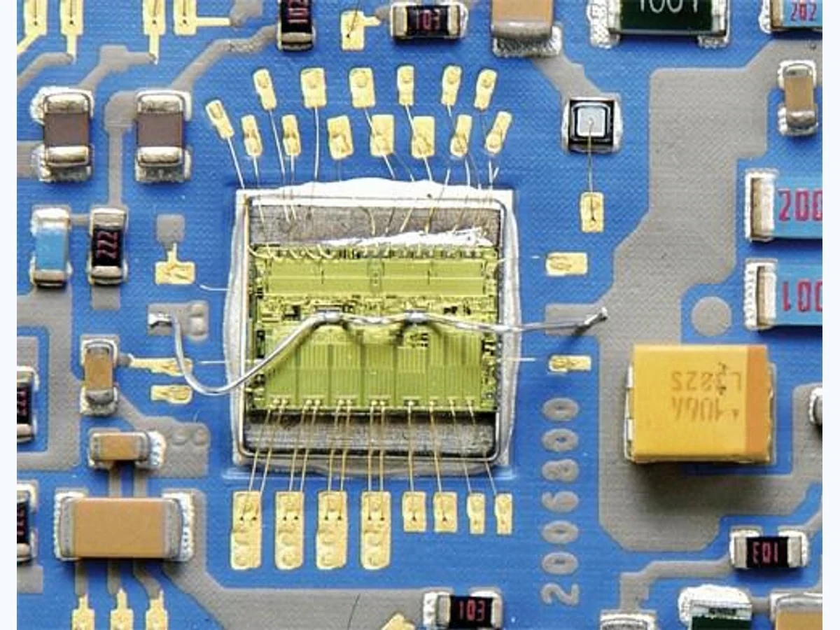
A die-attach area on ceramic is both a mechanical joint and a thermal interface. Its geometry controls where adhesive or solder can spread, how the die is supported and how heat enters the substrate. Selecting an attachment material is only one part of the problem. The drawing also needs a usable footprint, a bondline target, surrounding keepouts and a method for evaluating voids. Define these features from the device function and assembly sequence so an apparently neat joint does not conceal poor thermal contact or stress concentration.
Key design decisions
- Separate the die outline, permitted placement region, attach-material footprint and final fillet envelope.
- Evaluate void position as well as total void area, especially beneath concentrated heat sources.
- Agree how bondline thickness will be established and measured after the complete cure or attachment cycle.
Define four different boundaries on the drawing
The die outline describes the solid component. The attachment footprint describes where material should remain beneath it. The placement region allows for assembly position variation. The fillet envelope describes material that may extend beyond the die after placement. Treating all four as one rectangle leaves important decisions to the assembly operator.
Include nearby wire-bond pads, conductor clearances, overglaze steps and housing features. An adhesive that spreads into an adjacent bonding region can create a surface problem even if it does not form an electrical short. A footprint sized only from the die width may ignore the dispensing pattern and the path through which trapped air escapes during placement.
Choose bondline thickness as a process variable
A thinner bondline may reduce the thermal path through a low-conductivity attachment layer, but the practical minimum depends on flatness, particle size, dispensing behavior and the adhesive's cure requirements. A thick layer can accommodate some surface variation while increasing thermal resistance and allowing more die movement before cure. Neither direction is automatically better.
Bondline thickness affects adhesive cure and adhesion and must be controlled for the selected grade. Apply the actual adhesive grade's requirements, not a generic thickness copied from another assembly. Define whether the target is measured under the die center, at several corners or as a distribution across a section.
Calculate the attachment contribution before optimizing the ceramic
For an initial through-thickness estimate, use the attachment thickness, effective conducting area and appropriate thermal conductivity. Keep the conductivity value tied to the cured material and the relevant temperature. The calculation assumes heat flows approximately normal to the joint; local heat sources and voids can require a spreading model.
A hypothetical joint with twice the bondline thickness has twice the layer resistance when conductivity and area remain unchanged. Halving the nominal void-free area also doubles this simplified resistance. Real voids are not uniformly distributed, so this area correction cannot establish the peak die temperature. Use it to identify sensitivities and select measurements, not to certify the final assembly.
Rattach = t / (k × A)
- Rattach: attachment-layer thermal resistance in K/W
- t: cured bondline thickness in m
- k: attachment thermal conductivity in W/(m·K)
- A: effective conducting area in m²
Uniform one-dimensional conduction through a homogeneous layer; contact resistance and lateral spreading are evaluated separately.
Interpret voids relative to the heat source and load path
A single central void beneath an active heat-generating region may matter more than the same area divided into small peripheral voids. A continuous void strip can also interrupt mechanical support. Report the void map with the die orientation and active-area location so the thermal and mechanical reviewers can interpret it.
Specify the inspection method and its detection limits. A projected area measurement does not reveal every three-dimensional interface feature, and a cross-section samples only its selected plane. Correlate complementary observations when a fault depends on a particular interface rather than accepting a single percentage without context.
| Observation | Possible consequence | Next useful check |
|---|---|---|
| Central void under concentrated heat | Higher local thermal resistance | Compare active-area position and temperature map |
| Peripheral fillet with empty center | Misleading external appearance | Inspect the buried attachment region |
| Large corner thickness difference | Die tilt and uneven mechanical support | Measure flatness and placement force |
| Void band along one edge | Directional support loss | Review dispense and air-escape sequence |
Coordinate dispensing, placement and cure support
Choose the dispensing pattern with the die area and material flow in mind. The goal is controlled coverage and air release, not maximum initial material volume. Record dispense mass or another repeatable quantity when comparing patterns. A visually identical dot can vary in volume if its height changes.
Placement speed, force and dwell can change spread and die tilt. The support beneath the ceramic must also remain stable while the die is placed. During cure, restrain the assembly only as needed to maintain geometry; an unnecessarily rigid fixture can introduce a different stress state from the final package. Track the actual temperature history experienced by the joint.
Account for metallization and overglaze topography
The die may sit over a metal pad, bare ceramic or a combination of surface levels. A printed edge or overglaze step can create a local standoff and alter the attachment thickness. Define the permitted surface beneath the die and keep a protected transition away from the active bondline where the design permits.
Inspect the surface before attachment for debris and handling residue. Cleaning must suit the ceramic, metallization and attachment chemistry. A stronger solvent is not automatically a better preparation method. If a cleaning change is proposed, compare wetting, cured adhesion and electrical behavior using the same attachment process so the cause of any change remains identifiable.
Review expansion mismatch over the full temperature excursion
The die, attachment and ceramic generally expand differently. Their relative movement depends on temperature change, die dimensions, attachment compliance and how the surrounding package restrains the ceramic. Larger lateral die dimensions can increase mismatch displacement even when the bondline material is unchanged.
Begin with the maximum distance from the neutral region to the die edge and estimate the differential expansion over the intended temperature excursion. This displacement is not itself a stress result, because adhesive modulus and time-dependent behavior affect the response. Use it to identify assemblies that need a more detailed mechanical model or comparative thermal cycling.
Link the inspection record to functional performance
An attachment acceptance plan should connect appearance, coverage and thickness to the device's thermal and mechanical requirements. Preserve the assembly orientation, material lot, dispense condition and cure record alongside inspection images. Without those details, a later thermal change may be impossible to trace to the joint.
When thermal performance is poor, compare the bare ceramic path, the attachment interface and the external heat sink separately. Increasing substrate conductivity cannot remove a large attachment bottleneck. For a drawing review, provide the device heat map and mounting boundary as well as the nominal power so the important interface can be assessed.
Send the die-attach interface inputs
Provide the geometry and thermal boundary needed to evaluate the attachment area.
- Die outline, active heat-source location, placement allowance and surrounding electrical or bond-pad keepouts.
- Attachment material grade, proposed dispense pattern, bondline target and complete cure or soldering sequence.
- Ceramic surface condition, metallization steps, flatness information and package support arrangement.
- Void-inspection method, temperature limits, power distribution and required mechanical loading conditions.
The drawing-upload form loads as you reach this section.