
Overview
Hybrid microcircuit packaging joins a populated ceramic circuit to mechanical protection, electrical feedthroughs, heat removal, atmosphere or encapsulation, external leads, and system assembly. The package cannot be selected from outline alone. Die attach, wire bonds, passive attachment, printed metallization, substrate support, lid or coating, seals, vents, getters where applicable, cleanliness, outgassing, corrosion, thermal expansion, vibration, shock, rework, inspection, and lifecycle validation interact. This guide explains the decision boundary without claiming that ChipSimple supplies any specific hermetic package, seal process, screening flow, military qualification, or reliability level.
Failure controls
These are review prompts, not evidence that every risk applies or that every test is available.
- A
Selecting an enclosure by outline and ingress appearance without mapping heat, stress, atmosphere, feedthrough, mounting and inspection.
- B
Calling a lidded package hermetic without a defined seal construction, leak method, acceptance and lifecycle evidence.
- C
Encapsulating wire bonds or components without controlling flow, cure shrinkage, adhesion, ionic contamination, voids and rework.
- D
Optimizing heat transfer while transmitting excessive CTE, clamp, flatness, vibration or lead-forming load into ceramic and joints.
- E
Testing electrical function only and missing latent wire, attach, metallization, seal, corrosion, contamination or thermal-interface damage.
- F
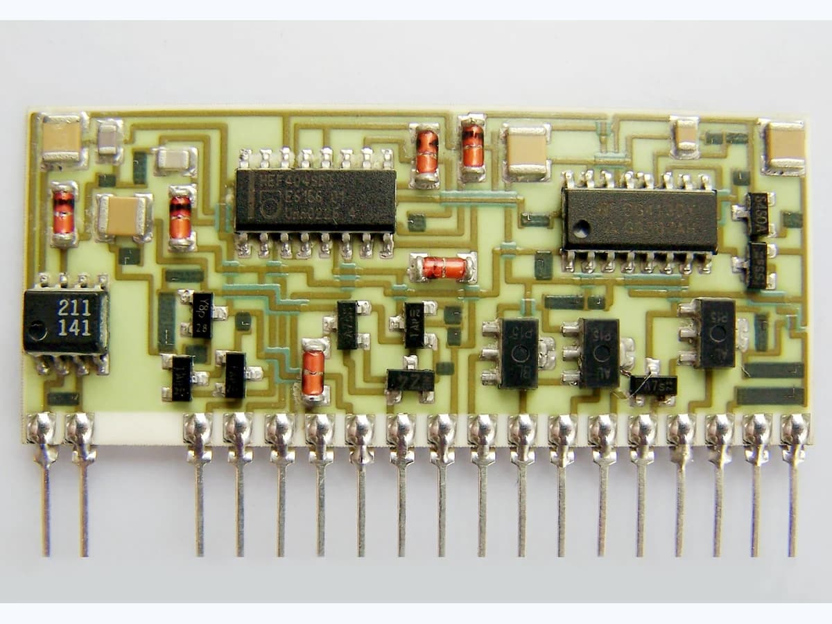
Using the populated-board photograph as proof of packaging, hermeticity, screening, environment, reliability or company capability.
Engineering review matrix
Each row links a design variable to evidence that can support a drawing or release decision.
| Variable | Control question | Verification route |
|---|---|---|
| Circuit and component boundary | Define die, passives, printed resistors/conductors, wire bonds, node voltages, power, heat sources, sensitive surfaces, clearances and functional acceptance. | Inspect and electrically/thermally test the populated circuit before and after packaging stages. |
| Package architecture | Specify cavity, lid, frame, encapsulant, coating, carrier, feedthroughs, leads, vents, seals, atmosphere, ground and external enclosure interfaces. | Review sectioned drawings and inspect production-intent construction against controlled materials and geometry. |
| Thermal path | Set dissipation waveform, attach layers, carrier, interface, mounting pressure, heat sink, convection, radiation, ambient and allowable local temperatures. | Correlate documented analysis with time-resolved temperature maps in the released mounting. |
| Mechanical path | Allocate CTE, stiffness, bond lines, cure, flatness, fasteners, lead forming, wire loops, vibration, shock, handling, substrate support and thermal cycles. | Measure geometry and inspect joints, wires, ceramic and attachments before and after representative loading. |
| Contamination and atmosphere | Define cleaning, ionic/particulate limits, residues, moisture, gases, outgassing, corrosion, bake, storage, internal atmosphere and seal requirements. | Use project-selected cleanliness, inspection, leak or environmental methods with configuration-linked records. |
| Assembly and rework | Control material lots, profiles/cures, sequence, tool access, handling, inspection holds, rework count/method, marking, packing and traceability. | Audit process records and repeat affected electrical, physical and environmental checks after rework. |
| Qualification and change | Define test sequence, sample configuration/size, acceptance, failure analysis, reports, substitutions, supplier changes, drawing revisions and system qualification owner. | Use baseline-versus-change assessment and require requalification for affected interfaces or failure mechanisms. |
Controlled model
Package heat-flow and interface comparison
Start with the protected functions and failure mechanisms. Lumped calculations can screen heat and stress paths, but actual interfaces, contact areas, voids, adhesives, wire loops, feedthroughs, enclosure geometry, gas or encapsulant, and mounting must be represented before a package decision is credible.
T_source ≈ T_ref + P θ_pathFirst-pass steady temperature estimate through a defined package heat path.
- Units
- T in °C or K; P in W; θ in K/W
- Use boundary
- Only for a stated steady boundary. Multiple sources, spreading, interfaces, radiation, convection, transient duty, voids and temperature-dependent properties require fuller analysis.
ΔL = (α₁ − α₂) L ΔTScreens differential free expansion between two joined materials.
- Units
- Length
- Use boundary
- Does not predict joint stress or fatigue; stiffness, geometry, cure, plasticity, gradients, constraints, defects and cycling require analysis or representative test.
Decision comparison
| Decision | Route A | Route B | Verification |
|---|---|---|---|
| Lidded cavity versus encapsulated assembly | A cavity can protect wire loops and surfaces while introducing lid, seal, atmosphere, feedthrough, internal contamination, condensation and leak-control questions. | Encapsulation can support or isolate features but adds cure, shrinkage, adhesion, ionic cleanliness, moisture, thermal, rework and wire-sweep risks. | Qualify the exact materials, geometry, process and environment with construction inspection, electrical checks, thermal mapping and relevant mechanical/environmental tests. |
| Rigid carrier attachment versus compliant support | Rigid bonding can improve positional control or heat transfer but can transmit CTE mismatch, flatness and mounting strain into brittle ceramic and joints. | Compliant attachment can reduce transmitted stress but changes thermal resistance, movement, bond-line control, damping, cleanliness and long-term material behavior. | Measure assembly geometry, temperature and electrical condition before and after thermal/mechanical exposures using the final mounting boundary. |
| Package-level protection versus system enclosure | A dedicated package can define a local environment and standardized interfaces but adds parts, processes, volume and inspection gates. | Relying on the product enclosure can reduce local packaging but makes the hybrid dependent on system sealing, cleanliness, mounting, airflow, service and assembly control. | Allocate each threat and verification owner explicitly; test the complete boundary that actually provides protection. |
- Hermeticity is a defined package-and-test claim, not a synonym for a metal lid or sealed appearance. Leak method, tracer, sensitivity, internal volume, acceptance, handling, atmosphere and lifecycle condition must be specified where hermetic performance is actually required.
- Packaging validation must preserve failure evidence. Electrical pass/fail alone can miss cracked ceramic, lifted metallization, weak wire bonds, die-attach void growth, corrosion, seal damage, encapsulant separation, lead fatigue, contamination and shifting thermal interfaces.
Hybrid package design workflow
The order makes assumptions and ownership visible before a result is promoted to a requirement.
- 01
Define protected functions and threats
List electrical nodes, sensitive die and films, dissipation, allowable temperatures, optical or fluid access if any, contamination, moisture, gases, particles, handling, vibration, shock, thermal cycling, radiation if applicable, storage, service, repair and end-system qualification ownership.
- 02
Map all package interfaces
Draw ceramic, printed layers, die attach, wire/ribbon bonds, passive attachments, underfill or encapsulant, lid or coating, frame, feedthroughs, leads, seal, internal atmosphere, thermal interface, fasteners, housing, connectors, ground and accessible metal as one controlled stack.
- 03
Analyze heat and stress paths
Allocate source powers and transient duty; model substrate spreading, attach layers, carrier, enclosure, convection and radiation. Review CTE mismatch, cure shrinkage, flatness, clamp load, wire-loop motion, lead bending, vibration modes, shock and ceramic edge or hole stress at tolerances.
- 04
Design assembly and cleanliness
Sequence die attach, component attach, wire bonding, cleaning, inspection, coating or encapsulation, cure, lid/seal, lead forming, marking, bake and packing. Define material compatibility, ionic/particulate control, outgassing concerns, rework limits, storage and traceability without inventing company processes.
- 05
Plan inspection and validation
Select drawing-linked visual, dimensional, electrical, thermal, bond, attachment, internal construction, leak where applicable, environmental, vibration, shock and lifecycle methods with specimens, fixtures, conditions, sampling, uncertainty, acceptance and failure-mode records.
- 06
Freeze configuration and responsibilities
Record package architecture, materials and revisions, suppliers, process sequence, interfaces, mounting, test methods, residual risks, system responsibilities, substitutions and requalification triggers. Public claims require company evidence, responsible technical review, and a directly relevant authorized photograph for the named construction.
Reference boundary
Public method sources
These sources support the engineering method and terminology used in this technical guide. They do not establish a ThickFilmPCB material list, capability limit, customer result, certification, or finished-product specification.
- 01MIL-STD-883 — Microcircuits test methods
Supports defined microcircuit environmental, mechanical, seal, inspection and bond test-method context when contractually applicable; it does not qualify a ChipSimple package.
- 02NASA Systems Engineering Handbook
Supports requirements, interfaces, verification, validation, risk and configuration management for the package as a system; it defines no manufacturing capability.
- 03KYOCERA Fine Ceramics electronic-components reference
Supports supplier-level ceramic material and package context only; typical properties and examples are not transferable product evidence.
Inputs for a practical review
Unknown values may be labelled unknown. The review should convert uncertainty into an explicit decision or validation task.
Send Drawings- 01
Circuit and package drawings, die/passive list, wire bonds, node voltages, current, power, timing, sensitive surfaces and functional limits.
- 02
Requested cavity/lid, encapsulant/coating, carrier, feedthroughs, leads, seal, atmosphere, ground, mounting and enclosure interfaces.
- 03
Die/component attach, wire process, printed stack, cleaning, cure, assembly order, rework, storage, handling and material restrictions.
- 04
Thermal sources, duty, allowable temperatures, heat sink/interface, pressure, airflow, radiation, ambient and fault states.
- 05
CTE, flatness, clamps, fasteners, lead forming, vibration, shock, thermal cycles, handling, service and repair loads.
- 06
Cleanliness, moisture, corrosion, outgassing, leak if applicable, visual, electrical, thermal, mechanical, environmental and lifecycle criteria.
- 07
Prototype/package variants, sample quantities, test sequence, failure analysis, reports, traceability, revisions, substitutions and qualification ownership.