
On this page
Every soldering and rework operation adds thermal exposure and can change a thick film termination. The joint may still look well wetted after the underlying metallization has thinned, lifted locally or become mechanically stressed. Define rework limits from the actual conductor, solder alloy, joint geometry and inspection evidence. A fixed number of reheats copied from another circuit is not a reliable limit for a different pad or material system.
Key design decisions
- Record cumulative solder-contact time and temperature history rather than counting only completed repair attempts.
- Inspect the pad before solder obscures it and after removal when rework is evaluated.
- Separate metallization consumption, adhesion loss, ceramic cracking and external-lead damage in the failure record.
Establish the condition of the unused termination
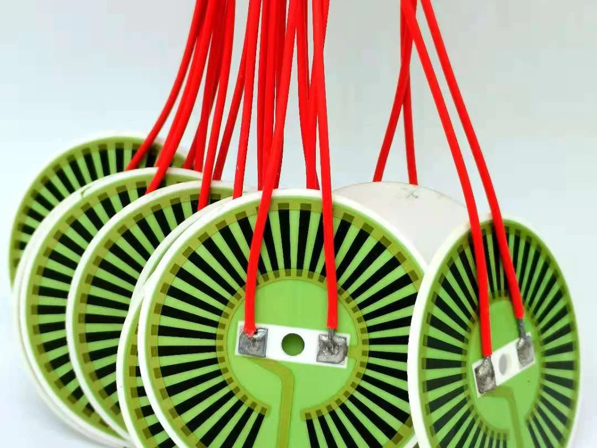
Before evaluating rework, document the fired pad geometry, accessible soldering area and any overglaze boundary. Confirm the conductor material and the thermal history already accumulated during circuit fabrication. A thin exposed edge beside an overglaze opening may be the limiting region even when the central pad is substantial.
Use representative unused pads for comparison. If the first assembly operation varies greatly, later results cannot be attributed only to rework. Record wetting behavior, joint appearance and electrical connection after the initial attachment, then preserve enough samples to distinguish the starting population from the repaired population.
Keep solder and metallization compatibility specific
Conductor systems differ in metal composition and in how they interact with solder. Silver-palladium, silver and gold-based regions should not be treated as interchangeable simply because they are conductive. Confirm the selected conductor grade, intended substrate and solder-exposure conditions from its controlled material data.
The solder alloy and flux also belong in the record. A change in alloy, bath condition or flux activity can change wetting and metallization interaction. The relevant exposure includes pre-tinning and component removal, not only the final attachment step. Do not assume a surface that still accepts solder retains its original mechanical integrity.
Count the complete rework exposure
Record the heating method, local preheat, time in contact with molten solder and cooling conditions. Several short attempts can produce a different history from one controlled attachment, even when the total elapsed repair time appears similar. The ceramic and neighboring components experience the local thermal gradient as well as the joint temperature.
Define the beginning and end of each recorded exposure clearly. Tool contact time is not always equal to time above solder liquidus, and a displayed tool temperature is not the pad temperature. Where the distinction matters, measure the representative assembly rather than relying on the equipment setpoint.
Remove the component without peeling the pad
Mechanical force during removal can damage a termination before metallization consumption becomes the limiting factor. A component or lead should not be pulled while a portion of the joint remains solid. The removal method must suit the joint geometry and provide support that does not bend the ceramic.
Record the direction of applied force and inspect the pad immediately after removal. A lifted region can be mistaken for poor wetting during the next attachment. If damage occurs, preserve the separated surfaces where practical. Their appearance helps distinguish failure within the solder, within the metallization or at the ceramic interface.
Distinguish the mechanisms that limit rework
The same final symptom, such as an intermittent connection, can result from several different mechanisms. A useful rework evaluation therefore includes both electrical and physical observations rather than a single pass/fail continuity result.
Photograph the original pad and the repaired joint at comparable magnification. Include an orientation marker and the attachment point so a local loss of metal can be matched to the electrical path. A different camera angle can otherwise make the remaining pad look larger or smaller without a real material change.
| Observation | Mechanism to investigate | Evidence needed |
|---|---|---|
| Pad becomes patchy after solder removal | Metallization consumption or surface damage | Before-and-after pad views and material history |
| Metal lifts with the removed lead | Adhesion or removal-force failure | Failure-surface location and removal sequence |
| Ceramic crack near a large joint | Thermal gradient or mechanical restraint | Crack origin and local heating record |
| Joint wets but resistance changes | Reduced path or altered contact | Defined electrical measurement boundary |
| Failure only when cable moves | Strain relief or joint compliance | Controlled cable-load observation |
Review local heating and expansion mismatch
A thick film pad is part of a ceramic assembly, so local heating can create stress beyond the solder itself. A large attached metal part can restrain movement while a small region is heated. The cooling sequence then adds another change in the stress state.
During manual soldering or rework, evaluate local temperature gradients and mechanical restraint in the actual circuit. Results from a different ceramic component do not establish a rework specification for this construction. Electrical continuity alone does not prove that the thermal operation caused no damage to the conductor, ceramic or attachment interface.
Build the rework allowance from a controlled comparison
Define the initial assembly and proposed rework sequence, then evaluate representative joints after each relevant exposure. Include electrical connection, wetting, pad condition and an attachment-strength method appropriate to the lead. Record the location of mechanical failures so a higher pull force is not accepted when the ceramic itself is breaking.
Use samples that represent the smallest pad, most constrained lead and most demanding neighboring geometry. A large isolated pad may tolerate handling that is unsuitable for a compact production joint. Keep the acceptance conditions tied to the drawing and intended use rather than declaring a universal number of allowable repairs.
Make rework history visible to later inspection
A repaired assembly should carry a traceable record of the affected joint, materials, sequence and inspection outcome. Later reviewers need to know whether a connection has seen the original attachment only or several removal and replacement operations. Without that history, a reliability comparison can mix fundamentally different populations.
If the acceptable exposure cannot be established for a particular joint, redesigning access or replacing the circuit may be preferable to repeated attempts. The decision depends on the product and application, but it should be made before an operator is forced to improvise under time pressure. The drawing-led review should identify these difficult joints early.
Send the soldering and rework history
Provide the actual material pair and joint sequence rather than only the requested repair count.
- Conductor material, fired pad geometry, overglaze opening and the ceramic assembly around the joint.
- Solder alloy, flux, heating method, preheat and measured or recorded exposure sequence.
- Lead or component geometry, removal direction, restraint and permitted rework operations.
- Pad photographs, electrical results and mechanical failure locations before and after the evaluated operations.
The drawing-upload form loads as you reach this section.