
On this page
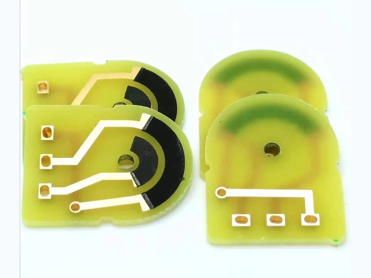
A polymer-carbon resistor printed on FR4 belongs to a different material and processing system from a fired ceramic thick-film resistor. Its electrical behavior depends on the selected ink, the board surface, the drying or curing sequence and the condition at measurement. Evaluating that combination requires a controlled process comparison. A ceramic firing recipe or a resistance value from an unrelated carbon formulation cannot define the behavior of the finished FR4 circuit.
Key design decisions
- Use the current technical data for the exact ink and substrate combination to establish the processing study.
- Measure actual board temperature and resistance after defined cooling and conditioning.
- Separate resistance during humidity exposure from resistance after drying or recovery.
Identify the ink system before specifying a thermal process
The term carbon ink covers formulations with different binders, solvents, conductive particles and intended substrates. Some are described by heat drying, while others have a curing reaction or another setting mechanism. Use the manufacturer's terminology and process instructions for the exact product, and preserve formulation identity when comparing results.
Specify drying or curing from the selected carbon ink and qualify the complete FR4 stack for that thermal exposure. Do not assign one schedule to every carbon resistor. An FR4 assembly must also tolerate the chosen thermal exposure and any later soldering, coating or assembly steps. Evaluate the complete stack rather than the ink in isolation.
Define what the ink actually contacts on the board
A resistor described as printed on FR4 may contact bare laminate, a surface treatment, copper termination or another coating. These surfaces can differ in roughness, contamination and wetting. Identify the actual resistor footprint and terminal transition, including any preparation or cleaning step.
Use boards from the intended fabrication route for qualification. A smooth laboratory coupon can behave differently from a production panel with ordinary surface variation. Record board storage and handling before printing, especially if moisture or residues are plausible contributors. If resistance changes when the board supplier or finish changes, compare the surface and process history before assuming that the ink lot is responsible.
Measure the board's thermal history
An oven setpoint is not the same as the temperature of the printed board. Loading, airflow, board thickness and fixture support affect heating and cooling. Establish the relevant temperature history at the specimen and relate it to the ink's specified processing conditions. Record when the required dwell begins rather than counting the entire time from insertion as equivalent exposure.
Compare candidate profiles using the same printed geometry and thickness measurement. Measure resistance after a defined cooling period so residual temperature does not obscure the comparison. A second thermal exposure can be informative, but a value that moves closer to target after additional heating does not by itself prove the original process was incomplete. The ink, substrate and transition regions may all respond.
Keep geometry and process contributions visible
For a uniform printed rectangle, sheet resistance multiplied by length-to-width ratio provides a starting estimate. Actual value also depends on processed thickness, edge formation and terminal effects. Use the ink supplier's stated reference thickness when interpreting sheet-resistance data, and measure the structure produced by the selected screen and process.
As a hypothetical calculation, a three-square geometry at an assumed 1,000 ohms per square gives 3,000 ohms before end corrections. If the measured processed sheet resistance is instead 1,100 ohms per square, the same ideal geometry predicts 3,300 ohms. This illustrates why changing artwork to compensate one thermal condition can be misleading if the underlying process is still moving.
Rbody ≈ Rs,processed × L/W
- Rs,processed is sheet resistance under the defined thickness, thermal history and measurement condition.
- L and W are the effective processed dimensions of the resistor body.
- Rbody excludes separately evaluated terminal contributions.
The printed body is approximately uniform and rectangular; the model is not a substitute for process-specific coupon measurements.
Distinguish exposure response from recovery
Humidity evaluation needs an explicit sequence: initial conditioning, baseline measurement, exposure, measurement during or after exposure, and recovery if required. State temperature and electrical bias as well as humidity. A reading taken inside an enclosure and a reading taken after a long transfer to a dry laboratory represent different specimen states.
Use a timed recovery record when resistance changes after removal. Retain the exposed-state reading even if the final dry value returns toward baseline. For the application, reversible change during use may matter as much as retained change after recovery. Avoid using an uncontrolled room-air reading to compare two lots that have spent different periods in sealed packaging or at different humidity.
Separate ink, substrate and measurement effects
Choose comparisons that hold two parts of the system constant while changing the third. Keep the same electrical boundary and timing, and inspect the printed surface before concluding that a resistance shift comes from the carbon network itself.
| Observed change | Controlled comparison | What it can distinguish |
|---|---|---|
| Value changes after an additional thermal cycle | Matched boards with and without the added cycle | Thermal-history dependence from ordinary measurement scatter |
| Different board lots give different values | Same ink and profile across characterized board surfaces | Substrate or finish effects from ink-lot effects |
| Resistance changes during humid exposure | Measure at defined exposure and recovery times | In-use reversible response from retained post-exposure change |
| High-value samples shift with fixture condition | Compare fixture blanks and controlled surface handling | Parallel leakage from the intended printed resistance |
| Only terminal-rich short resistors shift | Compare a length series with the same terminations | Transition contribution from the uniform body |
| Coated samples differ from bare samples | Measure before and after the coating sequence | Added processing and barrier effects together |
Evaluate protective layers as part of the process
A coating can change moisture access, surface leakage and mechanical loading, while its application may introduce solvents or another thermal cycle. It therefore needs a before-and-after comparison using the actual ink and board. A protective label alone does not establish compatibility or electrical stability.
Include the resistor-to-terminal boundary and nearby conductors in inspection. A coating that changes one region differently from another can alter the measured assembly even if the resistor body remains visually intact. Evaluate the complete sequence with the agreed exposure and recovery method. If the product later receives soldering or cleaning, include those steps in the same qualification path rather than treating the coated coupon as the finished assembly.
Specify the delivered condition clearly
The drawing and process agreement should name the substrate surface, ink identity, electrical target and measurement condition. Include relevant dimensions and terminal overlap, together with the permitted processing sequence. Keep a change-control link between ink, board finish, profile and protective layer because the qualified combination is the useful unit of evidence.
For an RFQ, provide the actual operating environment and subsequent assembly exposures. If humidity tolerance or long-term stability is a target rather than measured performance, state it as a requirement to evaluate. This supports a focused sample plan and avoids importing ceramic-firing assumptions into a polymer-carbon route whose behavior is determined by its own material system.
Provide the FR4 carbon-resistor process stack
Send the ink, board and exposure sequence together so their interactions can be evaluated.
- Ink product identification, current technical data and intended resistance range.
- FR4 board construction, actual surface under the resistor and terminal finish.
- Printed geometry, thickness information and measured board thermal profile.
- Baseline, humidity-exposure and timed recovery resistance data where available.
- Coating, soldering, cleaning and other assembly steps after printing.
The drawing-upload form loads as you reach this section.