
On this page
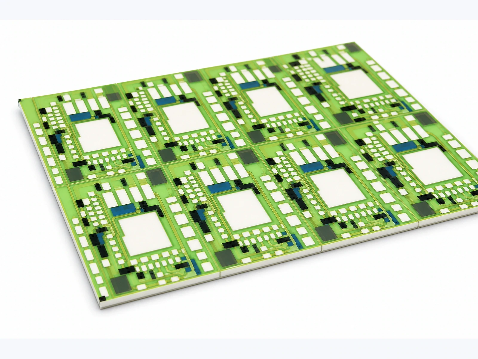
Laser-scribed ceramic panels need a controlled break sequence as well as a well-positioned scribe line. The first separation changes the support and stiffness available for every later break. Components, wire bonds, printed layers and loose particles can make a convenient manual sequence unsuitable for a populated panel. Plan how each strip and individual circuit will be supported, separated and collected. The objective is a predictable load path through the intended scribe region while keeping handling loads and debris away from functional features.
Key design decisions
- Choose whether separation occurs before or after sensitive assembly operations and document the reasons.
- Review support and bending direction at every stage, including the narrowest remaining strip.
- Keep the particle-control and part-identification process connected to the mechanical break sequence.
Specify the panel state at separation
A bare metallized panel and a panel carrying bonded components present different constraints. Population adds height, local mass and mechanically sensitive connections. A fixture that supports a bare face may touch a component or wire loop after assembly. Define the exact process stage at which each scribe line is broken.
Record which printed layers cross or approach the separation region. A protective glass layer may change the visible edge condition after breaking even when the ceramic fracture follows the intended path. Distinguish the electrical keepout requirements from the space needed for the fixture and handling tools. Do not assume the same separation arrangement works for every panel state.
Treat the scribe geometry as a matched process input
Specify the scribe geometry with the actual ceramic grade, panel thickness and intended separation method before completing the circuit layout. Obtain the actual scribe pattern, remaining section and orientation information relevant to the supplied panel.
A nominal depth percentage alone does not describe fracture behavior. Material thickness, local defects, scribe continuity and applied loading all matter. Keep any supplier process recommendation with its material and dimensional context. A successful break on one coupon does not establish a universal rule for a panel with a different thickness or layout.
Draw the support and bending arrangement for each break
Identify the contacts that hold the panel and the direction in which force is applied. Support should concentrate the intended bending action near the scribe without placing a hard contact on a fragile feature. An offset support can make the fracture travel through an unintended region even when the applied force feels small.
The relevant condition changes as the panel becomes strips and then individual circuits. A broad initial panel may be easy to locate, while a narrow final strip can rotate or slip in the same tool. Review those final operations explicitly. Do not optimize only the first break and leave the highest-risk handling to an improvised last step.
Compare row-first and column-first sequences
A row-first sequence and a column-first sequence can produce different intermediate strip shapes, component overhangs and access to fixture stops. Choose the order that keeps each remaining piece supported and makes part collection controlled. The better sequence is not necessarily the one with fewer hand movements.
For an asymmetric panel, annotate every operation rather than relying on a verbal instruction to break into strips. Include the part orientation after each rotation. Where two neighboring devices have tall or fragile assemblies, consider whether separating an earlier strip improves access or instead exposes unsupported devices to handling.
| Choice | Potential benefit | Risk to examine |
|---|---|---|
| Long strips first | Simple repeated alignment | Flexible or awkward final strips |
| Short strips first | Compact intermediate pieces | More reorientation and handling |
| Break before component assembly | Clear support surfaces | Additional individual-part handling later |
| Break after assembly | Panelized assembly efficiency | Component contact and particle contamination |
| Separate a perimeter rail first | Improved access to devices | Loss of locating or support features |
Control debris where the fracture is created
Ceramic particles can remain on a finished edge, fall onto a contact pad or become trapped beneath a component. The separation operation should have a defined collection surface and a cleaning method compatible with the circuit. Simply brushing a populated circuit may redistribute debris into less visible areas.
Inspect sensitive regions after the planned cleaning step, not only immediately after breaking. Identify whether a loose fragment is a removable particle or part of a damaged edge. For bare circuits, protect solderable and bondable regions during subsequent handling. For populated circuits, ensure the cleaning method does not load wire bonds, force liquid into a package or damage polymer materials.
Separate acceptable edge texture from functional damage
A scribed break produces a characteristic edge rather than a polished machined face. Define the functional damage boundary relative to conductors, locating features and required substrate dimensions. A rough region that remains outside the keepout is a different condition from a chip that reaches a termination.
Use consistent edge views to compare separation conditions. Record the location and direction of chips, cracks or unintended fractures. If damage repeatedly appears at a particular panel position, investigate the support and sequence before assuming random ceramic quality. A failure pattern can reveal an overhanging load or an incorrect tool contact that is invisible in the final detached part.
Run a sequence comparison with traceable panel positions
During process development, retain the original panel map and identify each separated part. Compare candidate break sequences using equivalent panels and the same inspection criteria. Record the operation at which each defect appears so damage introduced during a later cleaning or handling step is not attributed to the fracture itself.
A useful record includes panel orientation, fixture contacts, separation order, operator method and photographs of the intermediate strips. Measure the dimensional features needed for the installed assembly after separation. A circuit can appear undamaged yet fail to seat correctly if an edge fragment interferes with a locating surface.
Make the sequence reproducible in routine handling
A production instruction should show the initial panel, the intermediate pieces and the final collection arrangement. Define where hands or tools may contact the circuit and which surfaces must remain clear. Keep the orientation and identity system readable as rails and strips are removed.
Revisit the sequence when panel dimensions, component population, substrate thickness or fixture contacts change. These changes alter the load path even if the electrical artwork remains identical. The handoff should therefore include the mechanical panel revision as well as the circuit revision, with the inspection plan tied to the final separated state.
Send the panel and separation requirements
Provide the information needed to evaluate the complete singulation sequence.
- Panel drawing, material and thickness, scribe orientation, individual circuit outline and locating rails.
- Printed-layer and component maps showing sensitive features near each separation line.
- Proposed separation stage, fixture contacts, break direction, cleaning method and collection arrangement.
- Required final dimensions, edge-damage limits, traceability method and photographs of any recurring defects.
The drawing-upload form loads as you reach this section.