
On this page
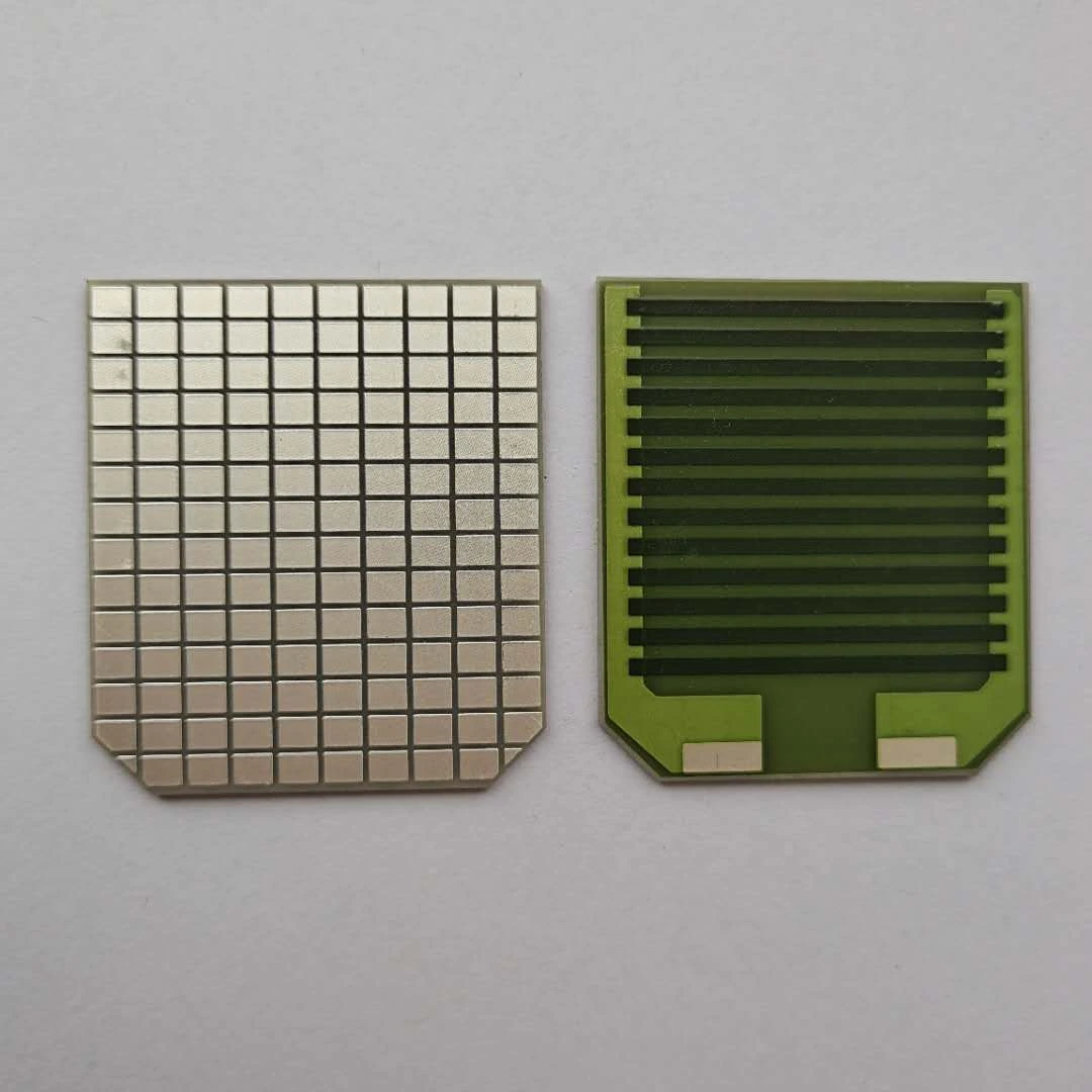
A serpentine resistor fits a long conductive path into a limited substrate area, but its turns and adjacent runs change more than the footprint. Resistance depends on how current crosses each bend; temperature depends on where that power can escape. A compact design should therefore be evaluated as a two-dimensional electrical pattern on a real thermal support. Counting centerline length alone cannot establish its power distribution or manufacturing robustness.
Key design decisions
- Compare candidate layouts at the same electrical function and mounting condition, not just the same footprint.
- Separate straight-run square count from the uncertain contribution of bends and terminations.
- Reserve space for printable gaps, repeatable turns, measurement access and any qualified trim region.
Start with the available envelope and a reproducible gap
Define the substrate boundary, terminal positions and keep-out regions before packing additional runs into the pattern. The usable area may be limited by attachment hardware, neighboring conductors, an edge seal or a mechanical clamp. A layout that occupies every available millimeter can leave no room for printing registration, inspection or an electrical correction.
Choose a provisional line width and spacing using demonstrated print results for the selected material system. Then count the number of runs that fit. The narrowest nominal gap is not automatically the useful gap: edge spreading, debris and local registration can reduce the actual separation. Inspect the fired or cured pattern at the relevant stage, because an artwork dimension does not describe the final electrical boundary.
Use straight sections to establish the first resistance estimate
For a uniform straight strip, the square count is length divided by width. Sum this quantity over the straight sections and multiply by measured sheet resistance. Keep bends and termination transitions as separate contributions. This prevents an uncertain corner assumption from being hidden in an apparently exact total length.
Suppose six straight runs are each eight millimeters long and 0.8 millimeter wide. They contribute 60 squares before the turns and ends are added. At an assumed sheet resistance of 100 ohms per square, the straight contribution is six kilohms. This example illustrates bookkeeping only. The final value requires the actual printed geometry and material measurement, plus the corrections established for the particular turn and terminal construction.
Rstraight ≈ Rs × Σ(Li/Wi)
- Rs is the measured sheet resistance for the relevant processed film.
- Li and Wi are the length and width of straight segment i.
- The sum excludes bends and transition regions.
Straight regions have approximately uniform thickness, width and material properties, with current flowing along their length.
Treat the inside of each turn as a separate electrical region
At a turn, the current does not follow one centerline with equal density everywhere across the width. Shorter paths around the inside compete with longer paths around the outside. This redistribution is why a bend can have a different effective resistance and local power density from a straight strip occupying the same outline.
An ideal sharp inside corner can produce mesh-dependent peak current density even when integrated losses converge. For a printed pattern, use the observed corner shape when evaluating local stress. A mathematically sharp artwork corner and a rounded printed corner are different models. Report integrated turn power and a physically meaningful temperature region rather than presenting an unconverged point maximum as a product prediction.
Account for neighboring runs in the thermal comparison
Runs placed close together share a substrate and can heat the same underlying region. The center of a tightly packed pattern may therefore operate at a different temperature from the outer runs even when every straight segment dissipates similar power. A lower overall footprint can make the heat-removal path more concentrated.
Compare candidate patterns using the same total power, substrate, attachment and ambient boundary. Then compare again under the actual drive condition. At fixed voltage, changing resistance changes total power; at fixed current, power changes in the opposite direction. A cooler photograph of a higher-resistance layout driven from the same voltage may reflect lower total dissipation rather than better thermal spreading. Preserve those conditions in the comparison record.
Choose the modification that addresses the observed limitation
Several geometry changes can improve one feature while worsening another. A larger turn radius consumes area; wider runs require more length to retain resistance; greater spacing can reduce the number of runs. Use a measured limitation to select the next comparison instead of applying every possible change at once.
| Observed limitation | Candidate change | Trade-off to measure |
|---|---|---|
| Local heating repeats at inside turns | Increase inner radius or revise the turn outline | Footprint and effective bend resistance change |
| Central runs are hotter than outer runs | Increase spacing or distribute the pattern over more area | Available square count may decrease |
| Narrow sections vary substantially in resistance | Increase width and add length where space permits | The larger pattern may alter thermal coupling |
| Gap defects appear after processing | Increase separation and inspect print edge formation | Fewer runs may fit within the original envelope |
| Final trim region lies beside a hot turn | Move the qualified adjustment region to a suitable straight area | Additional access and routing area are required |
Build a coupon set that separates turns from packing density
Include a straight reference, a sparse serpentine and a dense serpentine using the same line width and material process. Where possible, keep the number and shape of turns constant between the two serpentine patterns while changing spacing. That comparison helps distinguish turn contribution from thermal interaction between neighboring runs.
Measure resistance at low enough excitation to establish the initial electrical relationship. Then perform stepped-power observations under controlled mounting, allowing the same settling criterion for each specimen. Record final geometry and inspect the turn edges. If the dense pattern differs before appreciable heating, examine printing and electrical path effects before attributing the difference to thermal coupling. If the difference grows only under power, compare temperatures and support conditions.
Investigate a failed run at its actual location
An open circuit near a bend does not prove that the nominal radius was too small. A local neck, void, scratch or thickness reduction can place the highest stress there. Conversely, a broad temperature rise without visible geometry damage may point to poor substrate contact. Preserve electrical and optical records before cleaning or sectioning the specimen.
Map any failure location against the current-path model, print orientation and fixture support. Repeated failures at the same geometric feature are more informative than a single damaged sample. Compare intact neighboring turns as well as the failed one. This supports a targeted correction and avoids enlarging an entire design when the real issue is a local print or handling condition.
Specify a functional pattern rather than a length alone
The drawing should identify line width, gap, inner-turn geometry, terminal overlap and relevant tolerances. Include an electrical acceptance boundary and the permitted trim area where trimming is part of the route. A single total-path dimension is insufficient when local constrictions or registration determine performance.
Provide the drive waveform and thermal installation with the resistance target. Continuous operation and a short pulse can emphasize different parts of the pattern's thermal response. The agreed validation should examine the hottest meaningful regions, resistance change after the defined exposure and physical condition. Actual power and temperature limits remain dependent on the material, processed geometry and installation reviewed for the project.
Provide the serpentine layout constraints
Send the pattern and installation boundaries so packing density can be evaluated together with electrical and thermal behavior.
- Substrate outline, usable area, terminal locations and mechanical keep-outs.
- Nominal line width, gap, turn shape and any existing processed-pattern measurements.
- Resistance target, tolerance and proposed trim access.
- Voltage or current waveform, duty cycle and relevant pulse duration.
- Mounting, heat-removal surfaces and temperature observations from comparable conditions.
The drawing-upload form loads as you reach this section.