
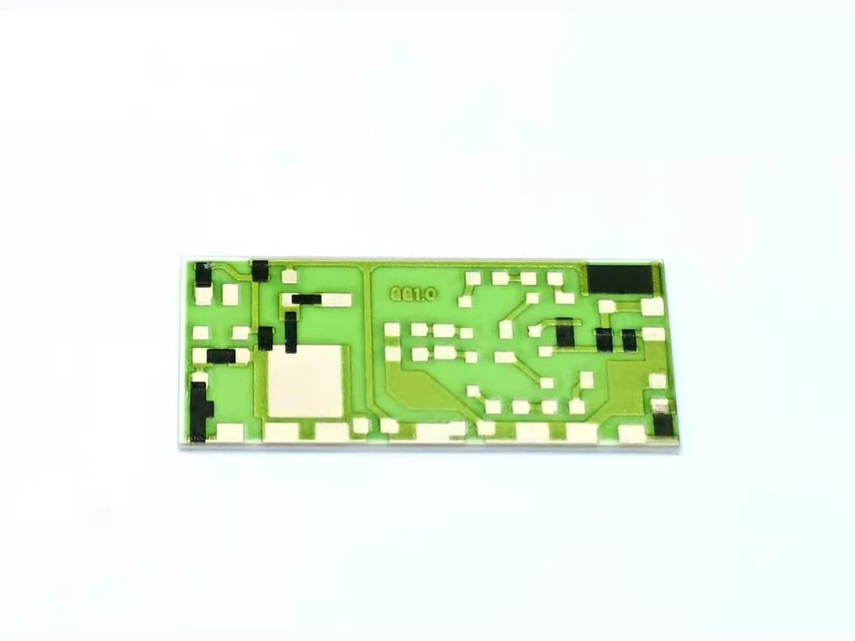
Overview
The familiar equation R = R□L/W is a useful first estimate for a uniform rectangular film, but a production printed resistor is not an infinite sheet bounded by ideal equipotential lines. Conductor overlap changes the active length and current injection; paste interaction and firing can create transition regions; corners redistribute current; narrow necks and serpentine turns create local density; printed width and thickness vary; substrate texture and screen transfer affect edges; laser trim intentionally reshapes the path; and probes, leads, protection, voltage, power, temperature, environment, and measurement fixture add their own terms. End and corner effects become more important as aspect ratio, feature scale, termination geometry, and current distribution depart from the supplier's characterization coupon. This page provides a geometry-correlation workflow rather than a universal correction factor. It does not claim a ThickFilmPCB sheet-resistance range, minimum width, corner rule, tolerance, trim accuracy, power density, voltage, TCR, noise, stability, or lifetime. Those require a named resistor-conductor-substrate system, production process, coupon family, measured distribution, and reviewed use boundary.
Engineering review matrix
Each row links a design variable to evidence that can support a drawing or release decision.
| Variable | Control question | Verification route |
|---|---|---|
| Sheet-resistance material system | Define exact resistor, conductor termination, substrate, compatible layers, nominal sheet-resistance family, lot or blend, thickness convention, and supplier test construction. | Review current TDS and measure process witnesses with the same material and thermal history as the design. |
| Effective body dimensions | Separate artwork, screen, wet, dried, fired or cured, and electrically effective length, width, thickness, edge, and active-area definitions. | Measure production-intent coupons and correlate image or profile data with resistance and panel position. |
| Termination end effects | Set conductor material and thickness, overlap, entry direction, pad geometry, registration, refires, diffusion or interaction allowance, and test access. | Use end-effect ladders, multiple lengths or transfer structures, and post-process inspection to separate body and transition response. |
| Corners and turns | Define inside and outside radius, angle, turn spacing, necks, adjacent heat, protection, print bridging, trim clearance, and local current path. | Inspect geometry and compare electrical and thermal response of straight, single-corner, and serpentine coupons. |
| Print and thermal process variation | Control screen, emulsion, paste state, printing, orientation, panel location, leveling, drying, atmosphere, firing or cure profile, cooling, refires, and protection. | Trend final geometry, thickness, value, visual defects, and witness response by lot, position, and process state. |
| Trim topology and sequence | Define no-trim or trim, cut type and placement, target, range, remaining path, equipment and optics, measurement current, stopping, debris, post-trim heat or protection, and inspection. | Compare pre-trim, immediate post-trim, settled, post-protection, post-assembly, and conditioned values with cut images. |
| Electrical and thermal loading | Specify voltage, current, continuous and pulse power, duty, ambient, mounting, heat path, nearby sources, gradients, abnormal states, and allowed temperature or change. | Map voltage or temperature where needed and measure resistance change through nominal, tolerance, transient, and fault conditions. |
| Measurement and acceptance | Define nodes, two- or four-wire method, probe pads, current, polarity, time, temperature, fixture, calibration, uncertainty, sampling, distribution, and decision rule. | Run traceable measurement-system checks and retain raw data, corrections, outliers, failure codes, and drawing-linked acceptance. |
Controlled model
Effective-square, transition, and local-loading model
Use the rectangular square-count equation as a baseline, then represent end and corner behavior with measured corrections for the exact material stack and geometry family. Keep nominal artwork, printed wet shape, fired or cured dimensions, and electrically effective geometry separate.
R_body,ideal = R□N = R□(L/W)Ideal resistance of a uniform rectangular body with N geometric squares.
- Units
- R in Ω; R□ in Ω/□; L and W in the same unit
- Use boundary
- Assumes uniform sheet resistance and thickness, straight parallel current flow, equipotential ends, no corners, and negligible contacts. It is a starting estimate, not a release equation.
R_total = R□(L_eff/W_eff) + ΔR_end,1 + ΔR_end,2 + ΣΔR_corner + ΔR_trimBookkeeping model separating effective body geometry from terminations, corners, and trim corrections.
- Units
- All resistance terms in Ω
- Use boundary
- Correction terms are not universal constants. They may interact and must be fitted only within a traceable material, process, thickness, geometry, temperature, and measurement domain.
J_nom = I/(Wt); P = I²R; q'' = P/(LW)Nominal current density, total electrical dissipation, and projected resistor-area loading for screening.
- Units
- J in A/mm² or A/m²; P in W; q'' in W/mm² or W/m²
- Use boundary
- Local current and temperature peak at transitions, turns, trim cuts, or thickness defects. These equations do not define allowable current, power, pulse, voltage, or temperature.
δR/R ≈ δR□/R□ + δL_eff/L_eff − δW_eff/W_effFirst-order sensitivity of a rectangular resistor to sheet resistance and effective length and width changes.
- Units
- Dimensionless, commonly %
- Use boundary
- Small independent perturbation form only. Include covariance, thickness, ends, corners, trim, nonlinear voltage or temperature response, measurement uncertainty, and process distributions separately.
Decision comparison
| Decision | Route A | Route B | Verification |
|---|---|---|---|
| Long rectangle versus serpentine | A long straight body keeps current direction simple but may consume length, approach practical aspect-ratio limits, and remain sensitive to end correction and width variation. | A serpentine compacts length but adds turns, inside and outside edge crowding, spacing, thermal coupling, print bridging, protection, trim access, and more complex corrections. | Print geometry ladders with straight and turned variants in the same material and process, then measure values, maps, defects, loading, and conditioned change. |
| Conductor overlap versus butt-style transition | Overlap can establish a robust current-transfer area but changes active length, local material interaction, firing, thickness, and transition resistance. | A minimal or different transition may reduce overlap intrusion but can increase registration sensitivity, edge discontinuity, current crowding, and interface risk. | Use supplier-compatible termination systems and measure the exact transition coupons after all refires and protection. |
| Geometry targeting versus laser trimming | As-processed geometry targeting avoids a cut but must absorb material, print, firing or cure, end, corner, and measurement variation in the initial distribution. | Laser trimming can move value toward target but adds cut topology, heat-affected or damaged regions, current crowding, trim range, measurement stopping, settling, protection sequence, and stability risk. | Compare pre-trim and post-trim distributions and inspect cuts after subsequent processing and use-condition exposure. |
- Define whether L and W are artwork, screen opening, wet print, dried print, fired or cured edge, or electrically fitted dimensions; mixing them corrupts correction data.
- Keep supplier test geometry visible when interpreting TDS sheet resistance, voltage coefficient, overload, noise, or power data; geometry dependence prevents direct transfer to arbitrary layouts.
Printed resistor geometry workflow
The order makes assumptions and ownership visible before a result is promoted to a requirement.
- 01
Define electrical requirement
Specify nominal resistance, tolerance state, reference temperature, TCR, voltage coefficient, noise, stability, continuous and pulse loading, source and load, frequency if relevant, measurement, trim, calibration, environment, and failure consequence.
- 02
Lock material and process system
Name substrate, resistor and conductor products, termination overlap, compatible dielectrics and protection, screen, thickness, printing, drying, firing or cure, atmosphere, refires, trim, cleaning, and later assembly exposures. Supplier data remain construction-specific.
- 03
Draw effective current paths
Mark artwork and expected final width, length, thickness, conductor entry, overlap, active body, corners, turns, necks, spacing, trim cuts, probe pads, edge and heat boundaries. Identify likely current crowding and inactive geometry.
- 04
Build geometry-correlation coupons
Vary aspect ratio, width, overlap, termination style, corner radius, turn count, orientation, panel position, and trim allowance over the intended design domain. Include straight reference bars and sheet-resistance witnesses with traceable lots and processing.
- 05
Measure geometry and resistance
Capture final dimensions, thickness or profile, line edges, defects, resistance at stated temperature and test current, termination contribution where separable, local voltage or thermal response where needed, and measurement uncertainty. Retain individual data.
- 06
Trim and condition representative parts
If trimming is used, control target, topology, measurement loading, stopping, cut geometry, debris, settling, protection, refire or cure, and later assembly. Apply electrical, thermal, humidity, mechanical, and aging exposures to nominal and boundary shapes.
- 07
Release a bounded design rule
Fit correction and tolerance models only within the validated material, thickness, geometry, process, trim, loading, and environment domain. Link rule version, coupon data, drawing, reviewer, acceptance, and requalification triggers.
Failure controls
These are review prompts, not evidence that every risk applies or that every test is available.
- A
Using R□L/W as a complete production equation while terminations, corners, thickness, trim, current crowding, and measurement are material
- B
Copying sheet resistance or power data from a supplier coupon whose substrate, geometry, thickness, firing, termination, and test conditions do not match
- C
Drawing a compact serpentine without characterizing turns, spacing, printing bridges, local heating, protection, and trim accessibility
- D
Using nominal artwork dimensions after print spread, firing or cure change, edge roughness, and panel variation alter effective geometry
- E
Trimming to initial value while creating a narrow hot path, damaged edge, debris, unstable cut, or inadequate later protection margin
- F
Publishing width, aspect-ratio, correction, tolerance, power, voltage, or stability rules outside a measured geometry and process domain
Reference boundary
Public method sources
These sources support the engineering method and terminology used in this technical guide. They do not establish a ThickFilmPCB material list, capability limit, customer result, certification, or finished-product specification.
- 01Heraeus R8900 Series thick-film resistor TDS
Supports that sheet resistance, TCR, voltage coefficient, overload, power, and noise data for a named resistor system are tied to specified substrate, termination, geometry, print, thickness, firing, and trim conditions; values are not universal.
- 02IPC-7092 official table of contents
Supports treating printed PTF resistor geometry, land compensation, serpentine configuration, printing, curing, coupons, testing, and reliability as an integrated design problem; detailed criteria require the licensed standard.
- 03NIST — Four-point sheet-resistance mapping system
Supports the measurement boundary that sheet resistance depends on a defined four-point method, probe configuration, sample geometry, position, and instrument range; it does not validate printed thick-film end or corner factors.
Inputs for a practical review
Unknown values may be labelled unknown. The review should convert uncertainty into an explicit decision or validation task.
Send Drawings- 01
Circuit drawing with resistor nodes, target value and tolerance, conductor entry and overlap, nominal body, turns, corners, trim area, pads, protection, and inspection datums
- 02
Exact substrate, resistor and conductor systems, dielectrics, overglaze or overcoat, screen, target final thickness, firing or cure, refires, trim, and allowed substitutions
- 03
Reference temperature and test current, TCR, voltage coefficient, noise, stability, continuous power, pulse and duty, source and load, and calibration requirements
- 04
Available area, minimum and maximum geometry, orientation, panel position, edge and hole clearance, thermal path, mounting, nearby heat sources, and assembly stack
- 05
Printing, drying, firing or cure, atmosphere, protection, cleaning, soldering or bonding, coating, rework, and later thermal or mechanical exposures
- 06
Operating and storage temperature, humidity, bias, fluids, contamination, vibration, shock, cycling, abnormal states, and life-validation sequence
- 07
Coupon matrix, prototype and lot quantity, geometry and electrical methods, uncertainty, trim records, sampling, acceptance, report, reviewers, and change triggers