
On this page
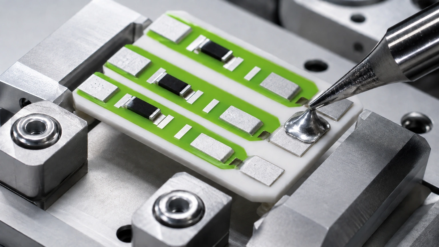
A solder land can meet its ceramic drawing yet receive paste or a preform off centre during downstream assembly. Component termination offset then consumes another side of the land. The relevant geometry is the common area among fired conductor, solder deposit and termination after all processes, not nominal pad size alone. A review keeps paste-print and preform routes distinct, measures their actual boundaries, and checks solder escape toward resistor, glaze and ceramic edges.
Key design decisions
- Define the fired land boundary and protected neighboring features.
- Stack solder-deposit and component offsets independently.
- Validate post-reflow joint geometry without inventing reliability claims.
Overlay fired pad, deposit, termination and keep-outs
Register the ceramic land, solder mask or glaze boundary if present, paste aperture or preform, component termination and adjacent conductor or resistor. State datums for ceramic printing and assembly placement. A camera alignment mark used by the placer must connect to the fired land coordinate. Define minimum exposed land, permissible solder spread and areas that must remain free. Avoid using nominal component body position when termination geometry controls the joint.
Calculate directional land remaining after offsets
For each side, subtract termination and deposit excursions from the fired land boundary. Use directional tolerances rather than one radial number.
L_rem,left=x_term,left-x_pad,left; L_rem,right=x_pad,right-x_term,right; A_common=A_pad∩A_solder∩A_term
- x_pad are measured fired-land edges.
- x_term are worst permitted termination edges.
- L_rem values are directional exposed-land margins.
- A_common is overlapping attachment area before flow redistribution.
Registered two-dimensional geometry; wetting, collapse and joint metallurgy need separate validation.
Calculate a land margin with two independent offsets
For illustration, a 2.00 mm fired land receives a 1.40 mm termination. With termination offset 0.18 mm right, nominal side margin 0.30 mm becomes 0.12 mm on the right and 0.48 mm left. If paste is independently offset 0.10 mm left, deposit-to-termination overlap becomes asymmetric. These values explain geometry and are not recommended pads, placement capability or joint acceptance.
Keep printed paste and preform placement as separate processes
Paste has aperture release, slump, volume and tack; a preform has cut-size, thickness and pick-place rotation. Reflow moves both according to wetting, surface condition, gravity and component force. Do not reuse a paste offset distribution for preforms. Record deposit mass or volume and placement coordinates before heating, then inspect the final joint. Ceramic conductor finish and cleaning state influence wetting and belong in the process genealogy.
Measure corners, terminals and neighboring keep-outs
Inspect fired pad dimensions and registration by panel location. Measure deposit centroid, area and height, component termination position and final solder extent. Include pads near ceramic edges, glaze steps, resistors and narrow conductor necks. X-ray or sections may support hidden-joint review but use allocated specimens and qualified interpretation. One top-view fillet cannot establish voiding, bond strength or life.
| Layer | Primary variation | Required record |
|---|---|---|
| Fired land | Print spread and registration | Edge coordinates |
| Paste or preform | Transfer, placement and volume | Pre-reflow boundary |
| Termination | Component placement and geometry | Directional overlap |
| Reflowed joint | Wetting and collapse | Final extent and defects |
Check solder escape and ceramic loading
Excess solder can bridge neighboring conductors, cover trim regions or contact an unintended coating edge. Insufficient common area can create incomplete wetting. A large preform or termination may transfer assembly force to brittle ceramic. Electrical continuity at room temperature does not prove thermal-cycle or mechanical reliability. The customer assembly owner defines joint design, metallurgy, profiles and acceptance. Preserve thick-film conductor and glaze compatibility through any proposed change.
Validate placement extremes through the authorized reflow process
Build specimens representing directional placement and deposit-volume limits, then run the specified atmosphere and profile. Measure final geometry and electrical connection; perform mechanical or environmental validation under the responsible plan. Compare paste and preform routes separately. Record component, solder, finish, cleaning, profile, fixture and lot. Rework creates a new thermal and surface history and must not be mixed with first-pass evidence.
Release the full attachment stack rather than pad dimensions alone
Control fired land, neighboring keep-outs, deposit definition, component termination, placement datums, finish, cleaning and thermal process. ChipSimple can review drawing-defined thick-film lands and compatible process inputs, while completed solder-joint reliability remains customer-owned. Reopen review after changes to land, paste, preform, component, finish, placement, reflow, glaze or substrate outline.
Connect the printed land to the assembled solder joint
A solder-pad drawing controls only part of the joint. Printed conductor spread changes the fired land outline; mask, glaze or dielectric registration determines the exposed wettable region; paste printing or preform placement establishes solder volume and initial offset. Review these boundaries in one overlay. Define the functional pad edge after firing and the permitted coverage opening. If the joint relies on a component termination, include its dimensional tolerance and placement window rather than centering an ideal package on the nominal land.
For paste assembly, estimate deposited volume from aperture area, stencil thickness and a bounded transfer factor. Treat that estimate as an input to trials because release, slump, flux loss and reflow wetting change the final shape. For preforms, include thickness, outline, placement clearance and movement during heating. Excess solder can bridge adjacent conductors or climb into a restricted zone; insufficient solder can leave incomplete contact or poor mechanical support. The right volume depends on joint design, alloy, finish, atmosphere and thermal profile, so no universal acceptance is implied.
Validation should use representative fired pads and the intended assembly route. Record pad dimensions, opening registration, deposit location, component placement, reflow profile identifier and final joint inspection. Cross-section or mechanical testing is applied only when the responsible plan requires it. Correlate defects with panel position and print direction to separate land geometry from assembly placement. RFQ inputs include conductor artwork, exposed-pad requirement, package drawing, solder material, deposit method, neighboring clearances and customer joint criteria. Reopen review after any land, opening, stencil, preform, alloy, component or reflow change.
Pad review should also address inspection visibility after assembly. A joint can cover the fired land edge, preventing confirmation of registration or contamination unless the process includes a pre-assembly checkpoint. Decide which characteristics are verified before soldering and which remain observable afterward. Establish image examples or dimensional rules for deposit offset without turning cosmetic variation into an unsupported reliability claim. For repaired joints, control heat exposure, added solder and cleaning, then repeat the relevant electrical and visual checks. Lot records should connect the substrate, component and assembly material identities so a defect investigation can separate printed-land, placement and reflow contributors.
Provide the fired land and downstream solder process
Assembly review needs all registered layers and their independent placement limits.
- Ceramic artwork, fired-pad tolerances, datums and neighboring features.
- Paste aperture or preform geometry, material, volume and placement limits.
- Component termination, placement, force, finish and cleaning.
- Reflow route, joint criteria, reliability plan and validation owner.
The drawing-upload form loads as you reach this section.