
On this page
The glass phase in a fired thick film layer contributes to how the printed material bonds to the ceramic and responds to later thermal and mechanical loading. Its role cannot be reduced to the visible color or gloss of the surface. The important interfaces may lie beneath a conductor, within a resistor structure or at a protective overglaze boundary. Review the material system, firing history and failure location together when investigating adhesion or residual stress.
Key design decisions
- Distinguish glass within a functional thick film material from a separately printed protective overglaze.
- Evaluate adhesion at the actual failed interface rather than treating every detached region as the same mechanism.
- Keep thermal expansion, layer thickness and attachment restraint in the analysis of residual stress.
Identify where glass participates in the structure
A fired thick film material can contain constituents that support bonding and the functional electrical structure, while a separate overglaze covers selected regions afterward. These are different locations and functions. Draw the layer stack and identify the interface under investigation before discussing the glass phase.
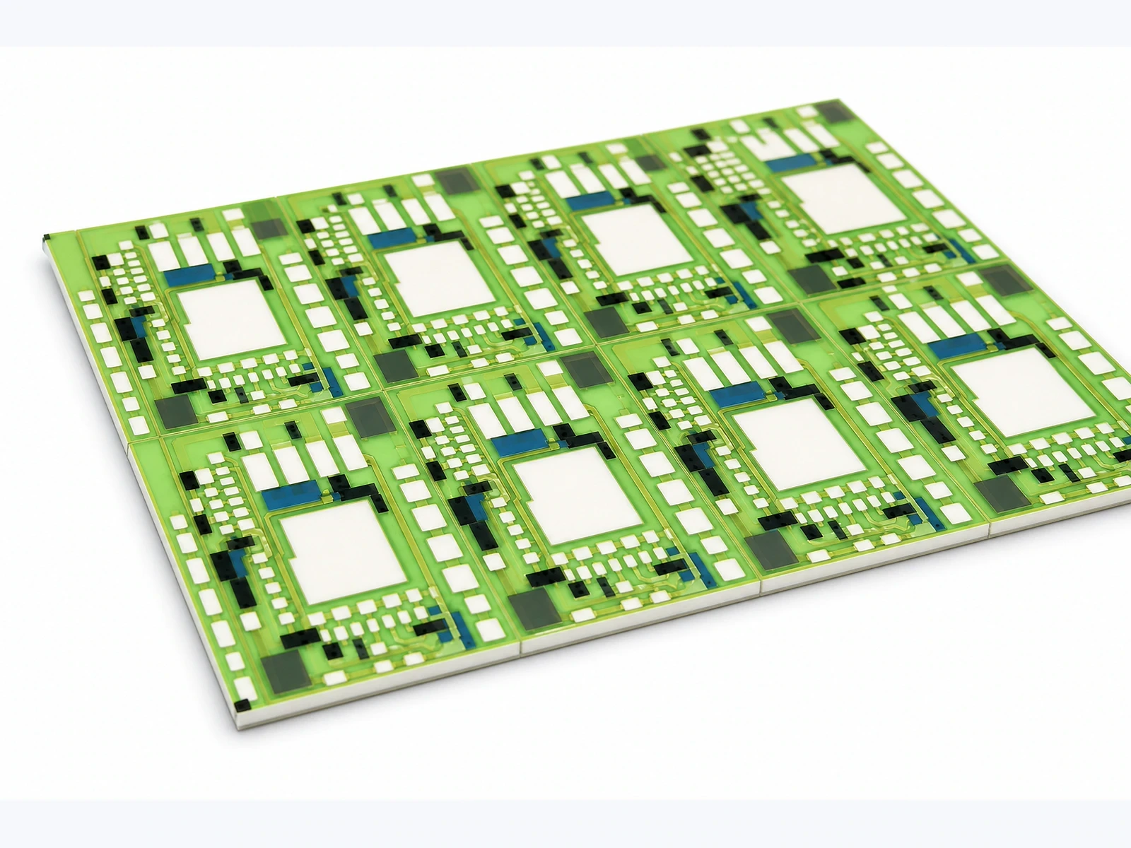
A protective green surface visible in a photograph does not reveal the composition or condition beneath it. Likewise, a conductor with an exposed metallic surface may still depend on a material-specific bonding system at the ceramic interface. Use the selected formulation and process documentation to establish the construction instead of inferring it from appearance.
Connect the interface to the firing sequence
Firing changes the deposited material from a paste into a bonded layer through a material-specific thermal process. The interface develops in the presence of the substrate surface, conductor or resistor constituents and the processing atmosphere. A single peak temperature does not describe that history.
Record heating, burnout, dwell and cooling along with later refirings. If adhesion changes after an additional layer is fired, compare the complete sequence rather than only the final operation. A material interaction can depend on cumulative exposure and layer order. The appropriate process window comes from the actual compatible system, not from a generic thick film temperature.
Separate interface preparation from material chemistry
Surface contamination, roughness, machining residue and the condition of a previously fired layer can affect the interface presented to the next print. A change in adhesion does not automatically mean the glass composition is unsuitable. First confirm that the compared surfaces and preparation histories are equivalent.
Use a controlled preparation comparison with the same material, printed geometry and thermal sequence. Evaluate the failure location as well as the measured attachment response. If one preparation causes separation at a different interface, the numerical result alone may hide the reason for the change. Preserve surface observations before coating makes the region inaccessible.
Review differential contraction after processing
After a high-temperature process, the layer and substrate cool together but may have different thermal expansion behavior. Their attachment constrains free contraction and can leave residual stress. Thickness, elastic behavior, geometry and cooling history influence how that stress is distributed.
A first screening calculation can estimate the free differential strain from an expansion-coefficient difference and temperature change. This is not the final stress, because the material response during cooling and the layer geometry matter. Use the estimate to identify a mismatch concern and decide what additional characterization is needed.
Geometry can concentrate the residual load at an edge or a change in coverage. Compare a broad continuous coating with a narrow island or an opening beside a termination; the boundary conditions are different even at equal average thickness. If cracking repeatedly follows a particular glass boundary, retain that geometry in a comparison coupon. A large uniform patch may miss the stress concentration that exists in the production pattern.
Δεfree ≈ (αlayer − αsubstrate) × ΔT
- Δεfree: difference in unconstrained thermal strain
- αlayer and αsubstrate: appropriate expansion coefficients
- ΔT: evaluated temperature change
Linear expansion over the selected range. Constraint, viscoelastic relaxation, phase changes and temperature gradients are not included, so this is not a stress or life calculation.
Locate separation before interpreting adhesion
The separated surfaces show which part of the structure limited the test. A layer can detach at the ceramic boundary, split internally or remain bonded while the ceramic fractures. These outcomes should not be grouped under one adhesion number.
| Observed location | Question to investigate | Useful evidence |
|---|---|---|
| Layer-to-ceramic boundary | Surface preparation or interfacial bonding | Matched failure surfaces and process history |
| Within the printed layer | Cohesion or internal defects | Section and fracture-surface observations |
| At an overglaze boundary | Layer compatibility or residual stress | Coverage geometry and thermal sequence |
| Within the ceramic | Substrate stress or local damage | Crack origin and loading geometry |
| Beneath an attached adhesive | Encapsulation restraint or removal damage | Attachment history and original surface condition |
Preserve fracture evidence through the investigation
Examine the glass and ceramic fracture surfaces together with the adjoining thick-film layers. The useful practice is to preserve orientation and distinguish original damage from preparation or removal artifacts. A cleaned or heavily handled fracture surface can lose important evidence.
Photograph the intact assembly and the first separated condition before cutting or polishing. Identify the suspected origin and choose a section that answers the mechanism question. Do not select only the easiest or most visually dramatic location. Compare the section with the original electrical or mechanical fault so the physical observation remains connected to function.
Check what a protective glass layer changes
Adding overglaze changes coverage, thermal exposure and the mechanical stack above a resistor or conductor. It can therefore affect an electrical value or a stress state even when the underlying artwork is unchanged. The selected material must be compatible with the existing layers and the intended sequence.
Establish the processing context for the selected resistor-overglaze system, then measure the actual circuit before and after the operation. Do not claim that every glass layer improves stability by the same amount or that a glossy appearance proves a dense, defect-free barrier.
Design a comparison that can identify the interaction
Separate the effects of added thermal exposure and added material where practical. An uncoated specimen receiving the same thermal sequence helps distinguish refiring effects from the presence of the overglaze. Keep specimen geometry and measurement conditions matched.
For mechanical comparisons, define the loading method and record where failure occurs. For electrical comparisons, use paired specimen identities and controlled temperature. The resulting evidence should indicate whether the next change concerns surface preparation, material compatibility, layer geometry or thermal history. Avoid changing all four at once and then declaring the original mechanism solved.
Send the glass-interface and thermal-history data
Provide the layer stack and the evidence identifying the affected interface.
- Substrate and thick film material grades, protective-glass layers and the order in which they are processed.
- Printed and fired geometry, coverage boundaries and all firing, refiring or assembly exposures.
- Surface preparation and handling records before each relevant layer is applied.
- Electrical changes, mechanical test configuration and oriented fracture or cross-section images.
The drawing-upload form loads as you reach this section.