
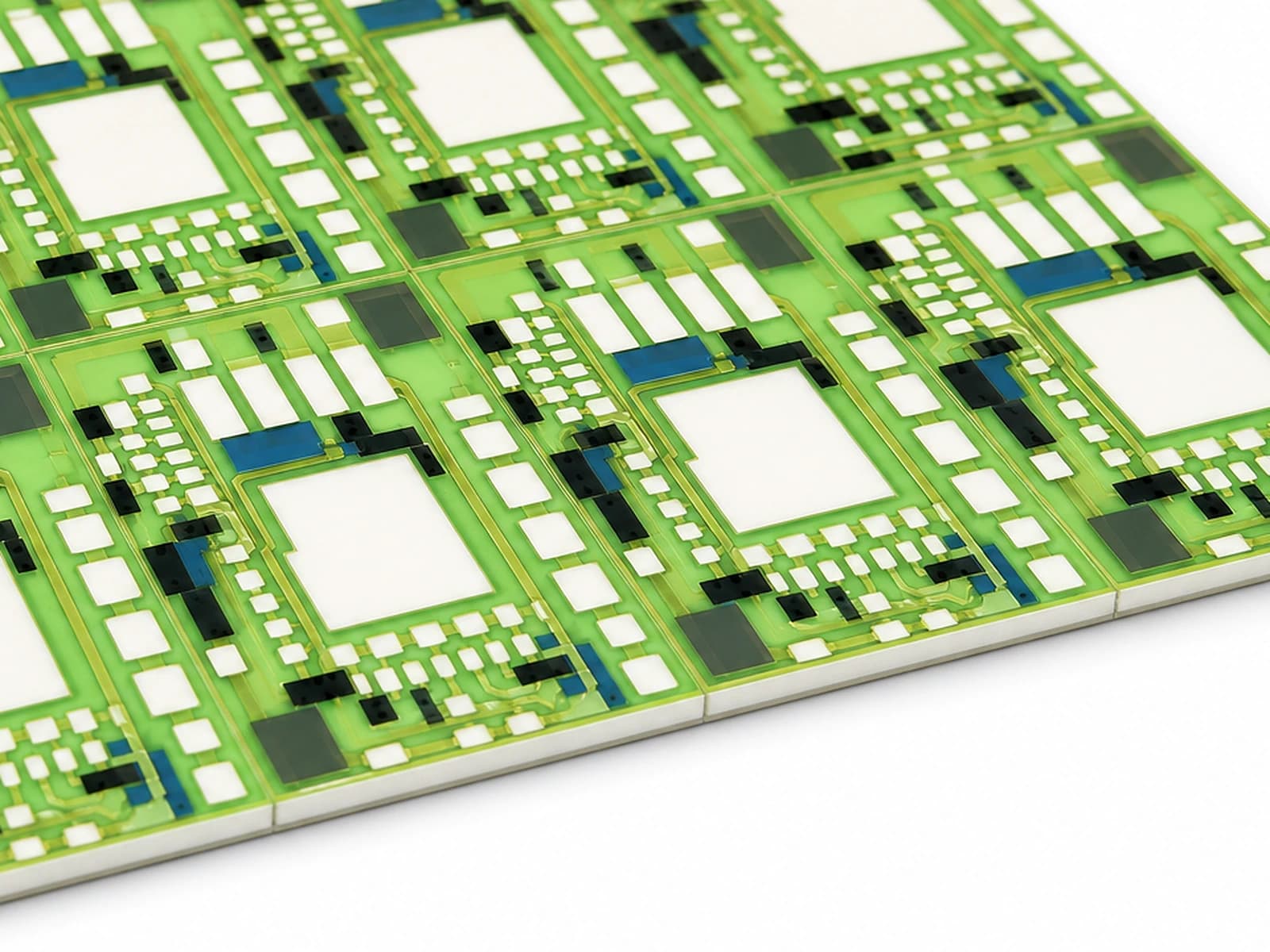
Overview
Fired glass encapsulation can protect selected thick-film features, but it also becomes part of the electrical, mechanical, chemical, thermal, and process stack. A named encapsulant may interact with a resistor, conductor, substrate, trim cut, crossover, solder pad, firing profile, and later assembly heat. Coverage can reduce direct exposure while openings, edges, pinholes, trapped residue, thickness variation, and thermal-expansion mismatch create new risks. Glass encapsulation must remain distinct from polymer overcoat and dielectric-crossover functions: each route has different processing and evidence. Selection begins with the protected failure mechanism and ends with validation of the complete production-intent stack.
Engineering review matrix
Each row links a design variable to evidence that can support a drawing or release decision.
| Variable | Control question | Verification route |
|---|---|---|
| Protection objective | Define the actual moisture, contamination, abrasion, handling, leakage, corrosion, trim, or mechanical risk and its acceptance metric. | Use a test that exercises the named mechanism on production-intent geometry rather than visual coverage alone. |
| Named glass material | Record product code, revision, lot, storage, conditioning, mixing, supported substrate/film compatibility, and approved alternatives. | Retain supplier and incoming identity and correlate results only to that controlled material. |
| Underlying stack | Specify substrate, resistor, conductor, dielectric, trim, layer order, prior/refire history, pad finish, and later assembly heat. | Measure electrical and physical state before and after every relevant encapsulation and downstream step. |
| Coverage geometry | Set overlap, windows, edges, holes, pad keep-outs, trim coverage, registration, layer count, thickness observation, and inspection datums. | Inspect fired coverage and defects at defined locations, magnification, lighting, sampling, and acceptance rules. |
| Electrical boundary | Define node voltages, polarity, spacing, leakage, dielectric function if any, capacitance concerns, ground, accessible metal, humidity, and contamination. | Use project-selected leakage, insulation and withstand methods separately from general protective claims. |
| Mechanical and thermal interaction | Include CTE mismatch, substrate thickness, gradients, local heat, firing, refires, assembly profile, bending, clamps, impacts, and exposed edges. | Inspect cracking, delamination, warpage, resistance change, and interface condition after representative thermal/mechanical exposure. |
| Environment and change control | Name humidity, condensation, fluids, cleaning, residues, abrasion, storage, bias, time, sampling, substitutions, process and drawing changes. | Use configuration-linked exposure results and repeat affected tests after material, geometry, process, or assembly changes. |
Controlled model
Protection-route and coverage comparison
Encapsulation is selected by a defined threat and interface map, not by gloss or color. Model electrical and thermal effects only after the actual fired layer and openings are known. Resistance shift and leakage must be measured before and after encapsulation because the protective process can change the protected circuit.
ΔR/R₀ = (R_after − R_before)/R_beforeQuantifies fractional resistance change across the encapsulation and firing sequence.
- Units
- Dimensionless, often %
- Use boundary
- The measurement temperature, voltage, timing, stabilization, trim state, handling and intervening process must be controlled; change is not automatically caused by glass chemistry alone.
C ≈ ε₀ ε_r A/tFirst-order capacitance of a uniform dielectric layer over area.
- Units
- F
- Use boundary
- A screening relation only. Printed thickness profile, edges, pores, electrodes, fringing, frequency, moisture, and multilayer geometry require actual analysis or measurement.
Decision comparison
| Decision | Route A | Route B | Verification |
|---|---|---|---|
| Fired glass encapsulation versus polymer overcoat | A fired glass route uses a compatible high-temperature material and firing step that can affect underlying films, trim, stress, and later assembly. | A polymer route is cured at lower temperature but introduces different chemistry, moisture, adhesion, solvent, cure, thickness, and service limits. | Qualify each named route separately on the complete circuit with process, electrical, mechanical, environmental, and assembly evidence. |
| Full coverage versus selective windows | Broad coverage can shield more surface but may cover pads, add stress, trap contamination, or change heat and electrical behavior. | Selective openings preserve contacts, trim access, or heat transfer but make registration, edge quality, creepage, cleaning, and transition zones critical. | Inspect fired coverage, openings, edges and defects, then test the actual electrical, assembly and exposure conditions at tolerance limits. |
- Encapsulation color and visible gloss do not identify material or validate coverage, adhesion, porosity, electrical insulation, or protection.
- Any firing temperature is a process condition only and must not become a product operating-temperature claim.
Failure controls
These are review prompts, not evidence that every risk applies or that every test is available.
- A
Choosing encapsulation from color or generic glass terminology without named chemistry, compatibility, process, thickness, and test context.
- B
Treating coverage as protection while overlooking pinholes, cracks, window edges, trapped residue, poor adhesion, registration, and exposed trim.
- C
Adding a refire after trimming or resistance calibration without measuring shift and stability through downstream assembly.
- D
Confusing fired glass encapsulation with polymer overcoat or dielectric crossover and transferring process or performance claims between them.
- E
Covering solder, wire-bond, adhesive, spring-contact, heat-transfer, probe, or rework regions needed by the final assembly.
- F
Using a product photograph as proof of material, dielectric strength, chemical protection, resistance shift, or company qualification.
Glass-encapsulation selection workflow
The order makes assumptions and ownership visible before a result is promoted to a requirement.
- 01
Define the protected risk
Identify moisture, contamination, abrasion, handling, bias, corrosion, trim exposure, surface leakage, mechanical damage, or another owned mechanism. State service environment, electrical potentials, temperatures, media, cleaning, assembly, and exact success criteria.
- 02
Map every material interface
Name substrate, resistors, conductors, dielectrics, trim cuts, prior and later firings, pads, finishes, joints, adhesives, housing and fluids. Mark compatibility as confirmed, conditional, unknown, or evidence needed rather than assuming all fired materials coexist.
- 03
Design coverage and openings
Dimension overlap, windows, pad and edge keep-outs, trim coverage, layer count, registration, wet/fired thickness observations, corner transitions, hole boundaries, venting, cleaning access, and inspection datums at tolerance extremes.
- 04
Control deposition and firing
Follow the named supplier's storage, mixing, printing, leveling, drying and firing instructions, then record screen, deposit, atmosphere, profile, loading, refires, cleanliness, handling, and traceability. Avoid unsupported universal process values.
- 05
Measure process interaction
Compare resistance, ratio if relevant, leakage or insulation, geometry, surface, coverage, adhesion evidence, cracks, bubbles, pinholes, trim condition and pad usability before and after encapsulation and downstream assembly.
- 06
Validate exposure and changes
Run project-relevant humidity/bias, chemical, thermal, mechanical, cleaning, abrasion, soldering or bonding and lifecycle conditions. Lock material code, revision, thickness/coverage, sequence, stack, inspection, acceptance, substitutions and requalification triggers.
Reference boundary
Public method sources
These sources support the engineering method and terminology used in this technical guide. They do not establish a ThickFilmPCB material list, capability limit, customer result, certification, or finished-product specification.
- 01Heraeus IP9038A resistor overglaze technical data sheet
Supports reviewing one named fired overglaze with resistor compatibility, trim sequence, printing, firing, coverage, storage and application tests. Its properties are not transferable company evidence.
- 02Heraeus IP9025W resistor overglaze product data
Supports the link among named overglaze, laser-trim behavior, resistance shift, fired thickness and processing only. It does not approve another stack or ChipSimple capability.
- 03Heraeus polymer thick-film materials brochure
Supports distinguishing cured polymer dielectric/protective routes from fired ceramic overglaze. Supplier examples and cure data do not transfer to this fired-glass selection.
Inputs for a practical review
Unknown values may be labelled unknown. The review should convert uncertainty into an explicit decision or validation task.
Send Drawings- 01
Protected feature and failure mechanism, service exposure, electrical bias, temperature, humidity, chemicals, abrasion, handling, and success criteria.
- 02
Substrate, resistor, conductor, dielectric, trim, glass, firing/refire, layer order, protection, finish, and approved material restrictions.
- 03
Dimensioned coverage, overlaps, windows, pad/edge/hole keep-outs, layer count, fired thickness observation, registration, and inspection datums.
- 04
Resistance/ratio shift, leakage, insulation, capacitance, adhesion, surface, cracking, pinhole, chemical, humidity/bias, and mechanical criteria.
- 05
Soldering, wire bonding, adhesive, contact, cleaning, cure, rework, mounting, local heating, and downstream assembly profiles.
- 06
Measurement sequence before/after trim, encapsulation, firing, assembly and exposure; instruments, sampling, uncertainty, failure recording, and reports.
- 07
Prototype variants, quantities, traceability, supplier/data-sheet revisions, drawing revision, substitutions, and requalification triggers.