
On this page
A bridge-completion resistor network can support an electrical check without applying a physical load to the sensor. Connecting a known shunt resistor across a defined bridge arm changes the bridge output by a calculable amount. That is valuable for checking the connected measurement path, but it does not exercise the sensor's mechanical load transfer. The specification must state both what the shunt checks and what still requires a physical calibration.
For a drawing-specific part, review the Custom printed resistor network construction, product evidence and quotation inputs alongside this method. Prepare the resistance and tolerance tool with your operating conditions.
Key design decisions
- Identify the exact arm and terminals across which the shunt is connected.
- Calculate the change from the actual bridge state rather than using a nominal resistance alone.
- Retain separate records for electrical span checks and traceable mechanical response.
Separate completion, sensing and shunt functions
A completion network supplies fixed resistive branches needed by a bridge containing one or more external sensing elements. A shunt resistor is a separate switchable branch that deliberately changes one arm. The fixed completion resistors, active sensor and shunt must not be treated as interchangeable parts merely because each is specified in ohms.
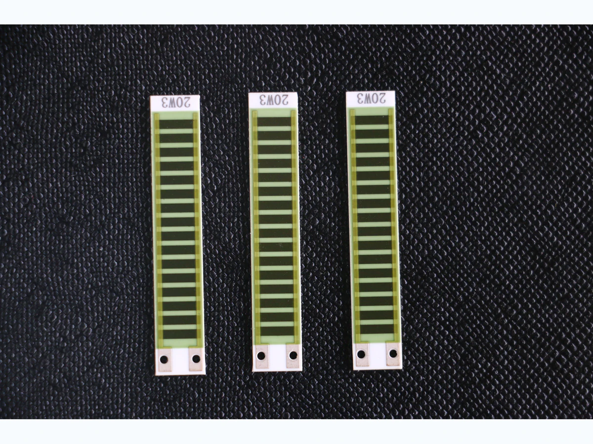
For a custom ceramic network, identify which of those resistors are actually printed and which are external. Include the switching connection and the measurement electronics in the schematic boundary. A passive completion network does not itself establish the gauge factor, force capacity or pressure sensitivity of the attached sensor. Those quantities belong to the transducer and its mechanical installation.
Fix the bridge labels and the output sign
Call the upper and lower left arms R1 and R2, and the upper and lower right arms R3 and R4. Apply excitation Vex from the upper supply node to the lower return. Define output as the left midpoint voltage minus the right midpoint voltage. With negligible receiver loading, output divided by excitation is R2/(R1 + R2) minus R4/(R3 + R4).
For four equal resistances R, both midpoints initially sit at half excitation. Shunting the lower left arm lowers the left midpoint and produces a negative output under this sign convention. Shunting an upper arm or changing the output polarity changes that sign. A label such as positive calibration is therefore incomplete unless the wiring and reported polarity are also defined.
Use the exact parallel-arm result
With a shunt Rs across R2, replace that arm by R2Rs/(R2 + Rs). For an initially equal bridge, the exact normalized output becomes minus R divided by twice the quantity R plus 2Rs. The approximation minus R/(4Rs) is useful only when the shunt is sufficiently large relative to the arm. Calculate its error before using it as a calibration target.
Assume all four arms are 1,000 ohms and the shunt is 249,000 ohms. The shunted arm becomes exactly 996 ohms, a change of minus four ohms. At 5 V excitation the exact output is approximately minus 5.01002 mV. The small-change quarter-bridge approximation gives minus 5.00000 mV and underestimates the exact magnitude by 0.2000 percent.
R2,sh = R2 Rs/(R2 + Rs); Vout/Vex = R2,sh/(R1 + R2,sh) - R4/(R3 + R4)
- R1 through R4 are the four defined bridge-arm resistances in ohms.
- Rs is the complete connected shunt-path resistance in ohms.
- Vout is left midpoint minus right midpoint; Vex is excitation at the bridge supply nodes.
The bridge is linear and resistive, the source voltage is defined at the bridge, receiver loading is negligible and the shunt is connected across the named arm.
Choose the shunt from a specified electrical output
For a balanced equal-arm bridge and a desired output magnitude x expressed in volts per volt, rearranging the exact result gives Rs = R(1 minus 2x)/(4x). The physical positive-resistance solution requires x between zero and one half. Practical checks normally use a much smaller imbalance, with the actual range chosen to stay within the connected acquisition channel.
For R = 1,000 ohms and x = 0.001 V/V, the exact shunt is 249,500 ohms. This is not the same value as the 249,000 ohm resistor that produces a four-ohm arm decrease. Specifying an equivalent resistance change, an electrical millivolts-per-volt output and an indicated mechanical quantity are different ways of defining the target; the conversion between them must be explicit.
Compare the shunt increment, not an uncorrected absolute reading
Record the settled output before closing the shunt, the output with it connected and the output after it is removed. A bridge can have an initial offset from its actual resistor values, temperature or sensor state. The useful electrical check is the predicted change between two defined circuit states, calculated with that state information where needed.
If the expected magnitude of the shunt-induced change is 5.01002 mV and the observed change is 4.96000 mV, their ratio is approximately 1.01008. That number can inform a gain-correction assessment only after the stimulus, excitation and connections are verified. It must not be used to conceal a wrong shunt terminal, a changing physical load or an unexpected offset step. Retain raw before-and-after readings alongside any corrected display.
Include the entire switched shunt path
The resistor value marked on a drawing is not necessarily the resistance connected across the arm. Switch resistance, leads and contact resistance in series with the shunt add to Rs. In the 249,000 ohm example, an added 50 ohms reduces the magnitude of the normalized shunt output by approximately 0.0200 percent. Whether that matters depends on the allocated check uncertainty, not on a general rule that contacts are always negligible.
The off-state path also matters: leakage or a partially connected shunt can alter the normal bridge before the check begins. Define the open and closed states separately. If the shunt is placed at an instrument connector rather than directly across the intended sensor arm, included lead segments may change both the stimulus and its interpretation. Analyze the actual terminals instead of assuming that any convenient pair reproduces the same bridge change.
Interpret each result within its actual boundary
An electrical check can be repeatable while the sensor's mechanical coupling has changed. Conversely, a failed check can arise in the switching or acquisition path without a change in the printed network. The following separation keeps corrective action attached to the observed mechanism rather than using one calibration label for the whole system.
| Observation | Useful conclusion | What remains separate |
|---|---|---|
| Normal bridge offset changes | The baseline electrical or physical state changed | Cause may be sensor load, temperature, resistance or readout offset |
| Known shunt increment changes | The connected electrical stimulus-to-output path changed | Verify shunt value and wiring before adjusting gain |
| Shunt increment is unchanged after mechanical modification | Electrical check remains repeatable | Mechanical load transfer and sensitivity still need validation |
| Equivalent load is assigned from an earlier physical calibration | The stored relationship can support a transfer check | Validity depends on the same transducer and defined calibration arrangement |
| Readout does not return after opening the shunt | The two test states were not fully reversible or settled | Resolve residual loading, drift or switching behavior before acceptance |
Keep the mechanical calibration record intact
A shunt electrically unbalances the bridge without reproducing strain transfer through adhesive, the flexure's response, mounting friction or pressure loading. Where an equivalent physical load is assigned to a shunt response, retain how that relationship was established with the particular transducer. Do not turn the calculated electrical response alone into a force or pressure calibration certificate.
The final network handoff should identify the bridge revision, measured arm and shunt values, excitation boundary, switch state, predicted increment and acceptance uncertainty. The sensor owner retains the physical calibration and installation limits. This division lets a printed completion network contribute a useful, reproducible electrical check while keeping the complete measurement system's responsibilities visible.
Provide the bridge and shunt-check circuit
Send enough detail to calculate the intended electrical stimulus and distinguish it from the sensor's physical calibration.
- Four-arm bridge schematic, printed versus external elements and defined output polarity.
- Measured or specified arm resistances, shunt value, switch arrangement and exact connection terminals.
- Excitation at the bridge, receiver loading, gain range and expected millivolts-per-volt check output.
- Before, during and after-shunt acquisition conditions, settling criteria and allowed check uncertainty.
- Physical sensor calibration record if an equivalent force, pressure or strain indication is required.
The drawing-upload form loads as you reach this section.