
On this page
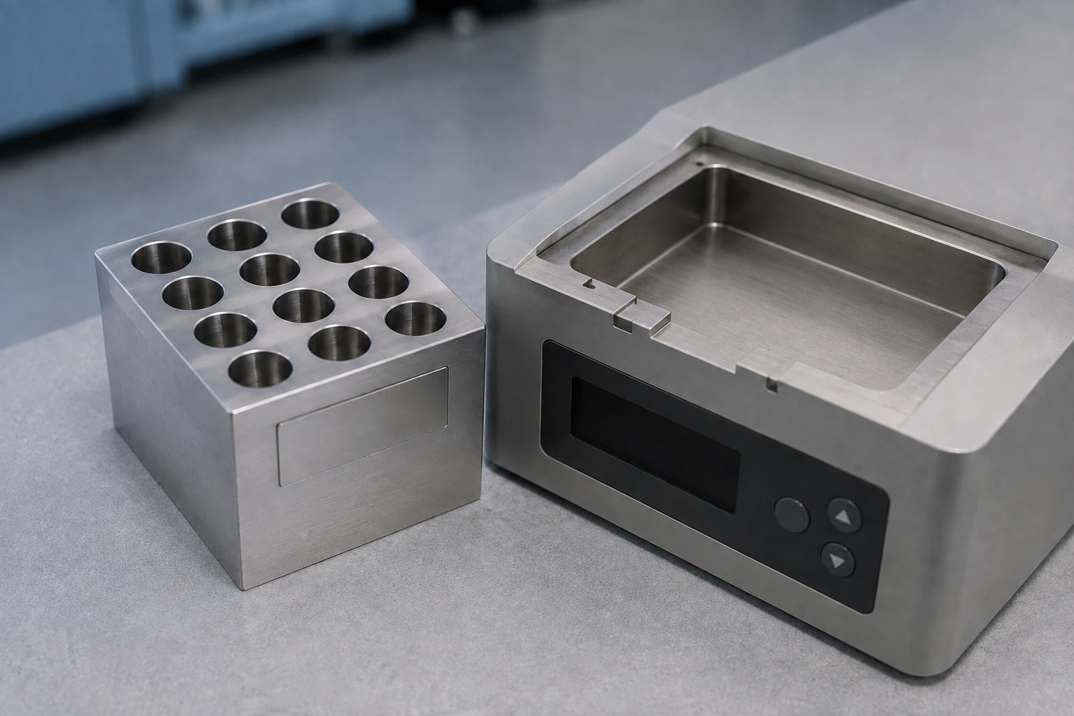
A removable thermal block is useful only if the instrument can distinguish a correctly installed, recognized module from a mechanically similar one carrying different thermal or calibration information. Reinstalling the same block and fitting another block are also different operations. For a printed heater integrated into a modular laboratory instrument, the interface specification should identify what moves with the block, what stays in the base and which evidence belongs to each assembled combination.
System boundary
The removable thermal module and instrument base, including locating and retaining features, candidate printed heater, temperature observation and calibration association. Sample chemistry, assay validity, regulated instrument qualification and operator authorization remain with the laboratory instrument owner. No commercial instrument is claimed to use a particular thick-film construction.
System integration decisions
- Separate the removable passive load block from a removable module that also carries its heater or sensor.
- Record module identity, seating state and calibration identity independently; recognizing a block does not prove full seating.
- Test same-block reseating separately from cross-block interchangeability before assigning a common acceptance statement.
Define which components move during a block exchange
A passive metal block placed on a fixed heated base has a different interface from a removable module containing its own heater and sensor. In the first arrangement, heat crosses a repeatedly disturbed base-to-block contact. In the second, the disturbed boundary may instead include electrical connectors and mechanical retention, while a heater-to-block bond remains intact. Do not use one exchange validation record for both architectures.
Commercial laboratory systems demonstrate that exchangeable blocks and block-associated calibration can be separate system features. That does not identify their internal heater technology or establish an appropriate construction for a new instrument. The OEM drawing should explicitly assign the heater, spreading body, sensor, sample holder and cover to the stationary or removable side before component selection.
Keep recognition separate from correct installation
A stored identifier answers which module the controller believes is present. It does not necessarily answer whether the mating faces are fully engaged or the retaining mechanism is in its required state. A connector can make contact before the thermal surface reaches its working position. Conversely, a passive block may seat correctly without carrying any electronic identifier.
Define the installed state in mechanical terms and state how the system observes or confirms it. If confirmation is an operator step, it belongs in the instrument workflow rather than being implied by automatic recognition. If an interlock is used, its relationship to the actual seating boundary must be validated by the equipment owner. Neither an identifier nor a normal heater resistance reading should silently substitute for that evaluation.
Attach calibration to the observable it actually corrects
A sensor correction addresses the response of an identified sensing channel under its calibration conditions. It does not automatically correct the thermal difference between the sensor and every sample vessel fitted to the block. Keep sensor calibration, block temperature characterization and sample-load correlation as separate records. Their applicability can change independently after an exchange.
Ask whether the sensor stays in the base or moves with the module. If it moves, the correction data must remain associated with that sensor even when the module is installed on another compatible base. If it stays, a module change can alter the sensor-to-load relationship without changing the sensor's own calibration. A software label such as calibrated block is too ambiguous unless these boundaries are named.
| Record | Identity it follows | What exchange can change |
|---|---|---|
| Sensor calibration | Sensor and measurement channel | Connector/channel association or applied coefficients |
| Block thermal characterization | Block, observation locations and installed boundary | Mating contact, base and surrounding heat loss |
| Sample-load correlation | Vessel, fill condition, location and closure | Carrier format or lid may change coupling |
| Installation verification | Specific seating event and retention state | Every physical removal creates a new event |
| Application acceptance | Complete approved instrument configuration | A component match alone does not preserve it |
Separate reading repeatability from reseating repeatability
Repeated observations without disturbing the module describe an installed state. Removing and reinstalling the same module introduces a new physical event. Replacing it with another module adds differences between modules. These are nested questions, not interchangeable sample counts. Ten readings from one installation are not ten independent demonstrations of successful exchange.
Retain the module identity and installation-event identifier with each observation. The test design should contain enough repeated readings within an event to distinguish observation noise from an installation shift. It should also contain multiple independent installation events if reseating is the decision. The required number follows the uncertainty and acceptance objective; a universal count would not reflect different fixtures, thermal loads or decisions.
Use return comparisons to detect changes that a simple swap hides
A comparison that measures block A and then block B can confuse a module difference with a gradual change in the base or environment. Returning to A after B provides an additional observation of the original combination. If the second A result has shifted, the evidence does not support assigning the full A-to-B difference to block identity. The return comparison reveals an ambiguity rather than automatically resolving its cause.
Keep the thermal load, observation method and permitted preparation state comparable for each installation. Record the elapsed time and any cleaning, cable movement or cover change. A second A installation is still a new seating event, so a shift may come from that event rather than time drift. Repeated or counterbalanced return sequences chosen by the validation owner can help separate these explanations; merely averaging A and B removes the information needed to diagnose them.
Compare the same thermal event after each exchange
A final temperature observed after a long hold can miss a change in how quickly the sample approaches that condition. Conversely, a different starting temperature can change apparent recovery time without changing the installed coupling. Define both the starting boundary and the observation event before comparing modules. Use the same location in the same load configuration, not whichever accessible point gives the cleanest trace.
If the application requires a stable sample interval, the qualification of that interval must refer to the sample-relevant observation, not simply the first moment that the base controller reaches its setpoint. Preserve the raw time record and the rule used to identify the interval. This allows a reseating comparison to distinguish a shifted endpoint from a changed transient rather than reducing both to one unexplained pass or fail.
Include carriers, covers and maintenance in the module boundary
A block can retain its serial identity while its load configuration changes. Different tube geometry, occupied positions, a replacement carrier or a changed cover can alter the path between the block and the material being conditioned. The instrument owner should decide which configuration attributes must match the thermal evidence and which variations are already covered by the approved application envelope.
Maintenance can disturb the same boundary that exchange validation is intended to control. Record replacement contact layers, surface repair and retention adjustments as changes, not merely as a note that the instrument was serviced. Do not increase clamp force to compensate for an unexplained temperature shift; the mechanical pressure and ceramic-support review remains a separate engineering task with its own limits.
Assign a clear outcome when identities or evidence do not match
The system should have an explicit disposition for an unknown block, a recognized but incompatible configuration, missing correction data and an installation that fails its required check. Those states need not all lead to the same operator message, but none should silently reuse the last successful block's coefficients. The instrument owner defines whether operation is prevented, restricted or returned for authorized review.
For a candidate printed heater, the supplier contributes its drawing, material-system identity and agreed component verification. The OEM establishes block interchangeability, software association and installed thermal behavior. The laboratory or application owner validates the sample procedure. Keeping these decisions separate permits a professional modular design review without representing the heater as a complete calibrated laboratory instrument.
Provide the removable-module architecture
Identify what is exchanged and which thermal evidence must remain valid after the exchange.
- Cross-section assigning heater, spreader, sensor, carrier, cover, retaining features and connectors to the fixed or removable side.
- Module and sensor identity scheme, calibration association and the handling of unknown or incompatible configurations.
- Sample-relevant observation location, thermal event, load configuration and the reseating or interchangeability decision to be demonstrated.
- Mechanical installation definition and existing same-block, cross-block and return-comparison records, with the owner of instrument acceptance.
The drawing-upload form loads as you reach this section.